Eureka AIR delivers breakthrough ideas for toughest innovation challenges, trusted by R&D personnel around the world.

A 3D system integrate structure and a manufacturing method thereof

A system integration, 3D technology, applied in semiconductor/solid-state device manufacturing, electrical components, electrical solid-state devices, etc., can solve the problems of low integration, high packaging cost, large size of the adapter board, etc.

Active Publication Date: 2018-12-14
NAT CENT FOR ADVANCED PACKAGING
View PDF5 Cites 11 Cited by
  • Summary
  • Abstract
  • Description
  • Claims
  • Application Information

AI Technical Summary

Problems solved by technology

[0005] In view of the relatively low integration level of the packaging structure based on the silicon interposer board in the prior art, the size of the interposer board is required to be large, which indirectly leads to the problem of high packaging cost. According to an embodiment of the present invention, a A 3D system integration structure, including:

Method used


Image

  • A 3D system integrate structure and a manufacturing method thereof
  • A 3D system integrate structure and a manufacturing method thereof
  • A 3D system integrate structure and a manufacturing method thereof

Examples


Embodiment Construction

[0042] In the following description, the present invention is described with reference to various examples. One skilled in the art will recognize, however, that the various embodiments may be practiced without one or more of the specific details, or with other alternative and / or additional methods, materials, or components. In other instances, well-known structures, materials, or operations are not shown or described in detail so as not to obscure aspects of the various embodiments of the invention. Similarly, for purposes of explanation, specific quantities, materials and configurations are set forth in order to provide a thorough understanding of embodiments of the invention. However, the invention may be practiced without these specific details. Furthermore, it should be understood that the various embodiments shown in the drawings are illustrative representations and are not necessarily drawn to scale.

[0043] In this specification, reference to "one embodiment" or "the...


PUM


Abstract

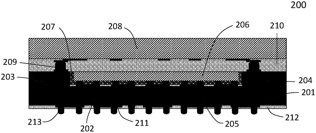
The invention discloses a 3D system integration structure, comprising: an adapter board; A first silicon through hole arranged on the front face of the adapter board; A second silicon through hole arranged on the front face of the adapter board; A cavity arranged on the back surface of the adapter plate; A first relayout wiring layer and a pad arranged on a bottom surface of the cavity, the firstrelayout wiring layer and the pad being electrically connected with the first silicon via; A first chip disposed within the cavity, the first chip electrically connected to the first relayout wiring layer and the pad; A plastic filling layer arranged around the first chip and having a gap between the bottom and the adapter board; A second chip arranged on the back surface of the adapter board, thesecond chip being electrically connected to the second silicon through hole; A second relayout wiring layer disposed on a front face of the adapter board; And a welding structure provided on the front face of the adapter plate, the welding structure being electrically connected to the second relayout wiring layer.

Description

technical field [0001] The invention relates to the technical field of integrated circuit packaging, in particular to a 3D system integration structure and a manufacturing method thereof. Background technique [0002] Mobile device manufacturers' demand for product miniaturization, low cost, and high integration has derived requirements for the cost, performance, integration and functionality of wafer-level packaging of related chips, and system-in-package solutions. In system-in-package, in order to realize the function of the package structure, several types of heterogeneous chips or passive devices are often involved in a package structure. Three-dimensional packaging technology has the advantages of combining plane and vertical space, and is a better direction for system-level packaging. [0003] Compared with the conventional packaging structure, the three-dimensional packaging technology based on silicon interposer technology has the characteristics of smaller package...

Claims


Application Information

Patent Timeline
IPC IPC(8): H01L23/538H01L21/768
CPCH01L21/76898H01L23/5384H01L23/5386
Inventor 徐成徐健戴风伟
Owner NAT CENT FOR ADVANCED PACKAGING
Why Eureka
Eureka Blog
Learn More