An IGBT overcurrent protection circuit and an air conditioner
An overcurrent protection circuit and circuit technology, applied in emergency protection circuit devices, circuit devices, emergency protection devices with automatic disconnection, etc., can solve problems such as IGBT burnout, achieve high reliability, realize overcurrent protection, and improve stability sexual effect
- Summary
- Abstract
- Description
- Claims
- Application Information
AI Technical Summary
Problems solved by technology
Method used
Image
Examples
Embodiment 1
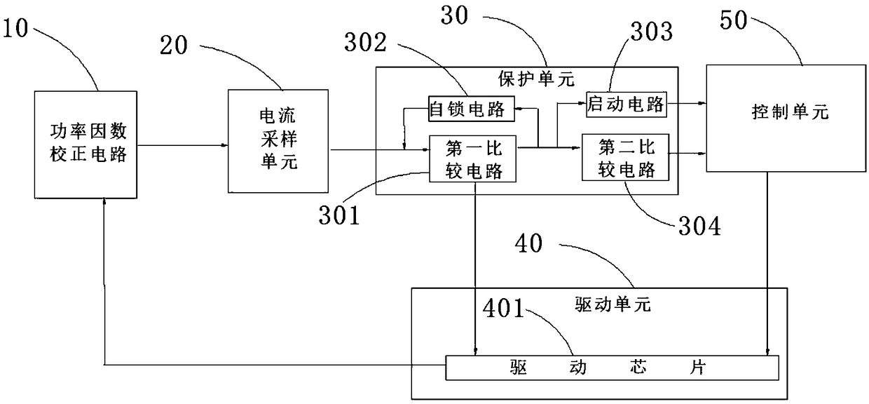
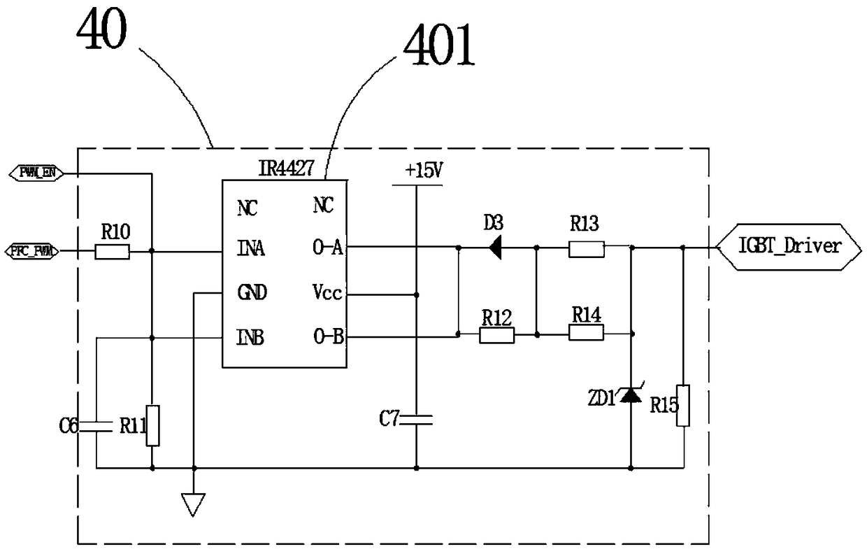
[0033] like figure 1 Shown is a schematic diagram of the IGBT overcurrent protection circuit in this embodiment; wherein, the IGBT overcurrent protection circuit includes a current sampling unit 20 , a protection unit 30 , a driving unit 40 and a control unit 50 .
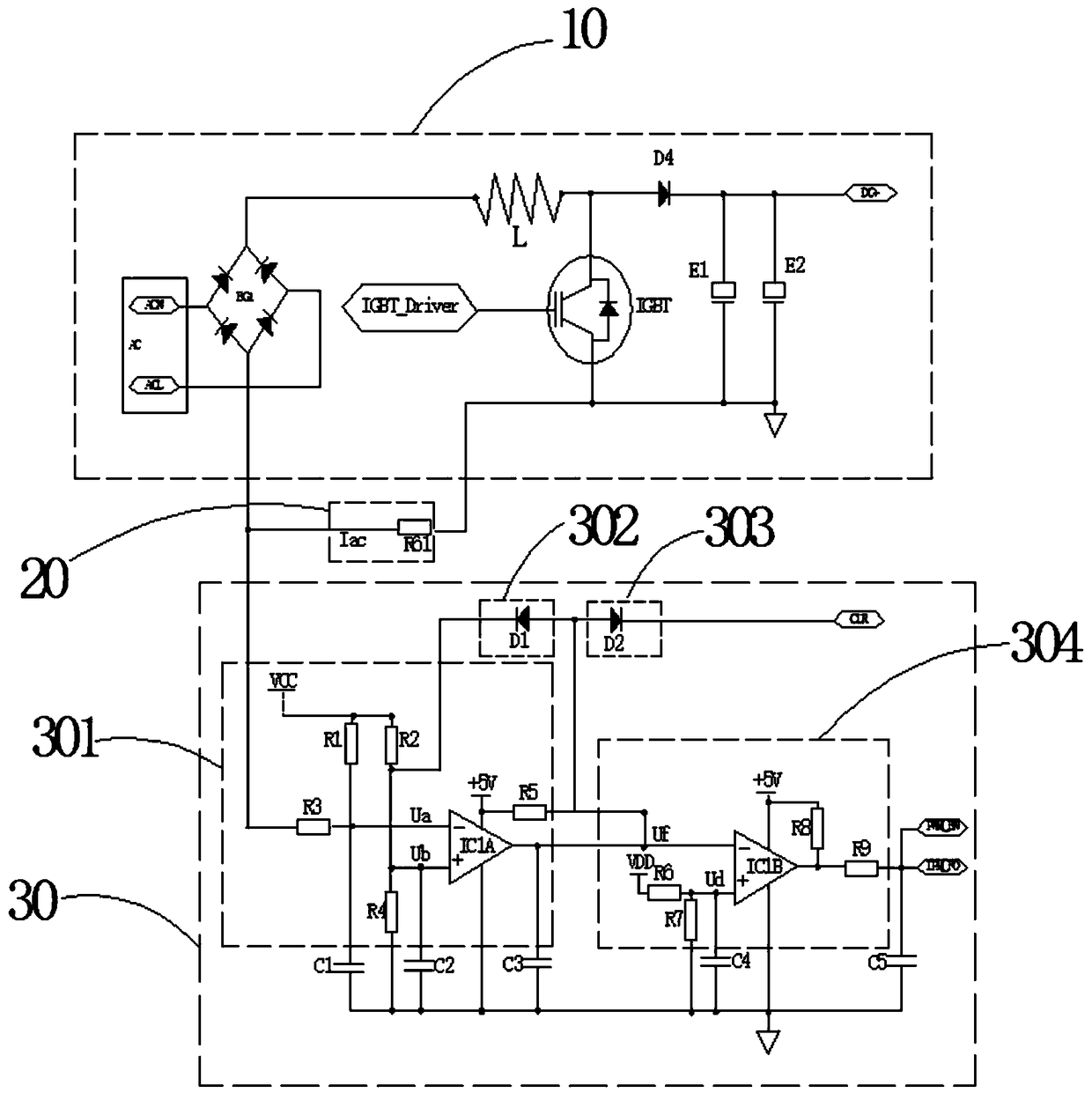
[0034] combine figure 2 As shown, the current sampling unit 20 is respectively connected to the emitter of the switching tube IGBT, the negative pole of the DC side of the rectifier bridge BG1 in the power factor correction circuit 10, and the input terminal of the protection unit 30. The output of the current sampling unit 20 to the power factor correction circuit 10 The current is sampled to obtain a sampled current, and the sampled current is sent to the input terminal of the protection unit 30 .
[0035] The protection unit 30 is used to convert the sampling current into a sampling voltage and compare it with the reference voltage to output a detection signal; the output terminal of the protection unit 30 is ...
Embodiment 2
[0041] As the above-mentioned IGBT overcurrent protection circuit, the difference of this embodiment is that, in combination with figure 2 As shown, the power factor correction circuit 10 in this embodiment includes an AC power source AC, a rectifier bridge BG1, an inductor L, a switching tube IGBT, a fourth diode D4, an electrolytic capacitor E1, and an electrolytic capacitor E2. The first AC input terminal of the rectifier bridge BG1 is connected to the neutral terminal ACN of the AC power supply AC, and the second AC input terminal of the rectifier bridge BG1 is connected to the phase terminal ACL of the AC power supply AC. The anode of the DC side of the rectifier bridge BG1 is connected to one end of the inductor L, and the other end of the inductor L is divided into two paths, one path is connected to the collector of the switching tube IGBT, and the other path is connected to the anode of the fourth diode D4. The cathode of the fourth diode D4 is the output terminal of...
Embodiment 3
[0043] As the above-mentioned IGBT overcurrent protection circuit, the difference of this embodiment is that, in combination with figure 2 As shown, the protection unit 30 includes a first comparison circuit 301, and the first comparison circuit 301 includes a first resistor R1, a second resistor R2, a third resistor R3, a fourth resistor R4, a fifth resistor R5, a first comparator IC1A, The first DC power supply VCC.
[0044] The first comparator IC1A includes a first input terminal and a second input terminal. The first input terminal of the first comparator IC1A is divided into two paths, one path is grounded through the fourth resistor R4, and the other path is connected to the first direct path through the second resistor R2. The current power supply VCC is connected. The second input end of the first comparator IC1A is divided into two paths, one path is respectively connected to the negative pole of the DC side of the rectifier bridge BG1 and the current sampling unit...
PUM
 Abstract
Description
Claims
Application Information
 - R&D
- Intellectual Property
- Life Sciences
- Materials
- Tech Scout
- Unparalleled Data Quality
- Higher Quality Content
- 60% Fewer Hallucinations
Browse by: Latest US Patents, China's latest patents, Technical Efficacy Thesaurus, Application Domain, Technology Topic, Popular Technical Reports.
© 2025 PatSnap. All rights reserved.Legal|Privacy policy|Modern Slavery Act Transparency Statement|Sitemap|About US| Contact US: help@patsnap.com


