Multi-coil wireless charging system and method

A wireless charging and coil technology, applied in electrical components, circuit devices, etc., can solve problems such as excessive wiring harnesses, mutual interference of signals, and waste of cost.

Pending Publication Date: 2018-12-14
SHENZHEN FANG XIN TECH
View PDF0 Cites 1 Cited by
  • Summary
  • Abstract
  • Description
  • Claims
  • Application Information

AI Technical Summary

Problems solved by technology

In the prior art, when a wireless charging transmitter charges multiple wireless charging receivers, multiple circuit modules connected in parallel are used. The disadvantage of this method is that the signals interfere with each other, and more power input terminals need to be laid and adapters, resulting in a great waste of cost, and requires too many wire harnesses, resulting in inconvenient use

Method used


Image

  • Multi-coil wireless charging system and method
  • Multi-coil wireless charging system and method
  • Multi-coil wireless charging system and method

Examples


Embodiment 1

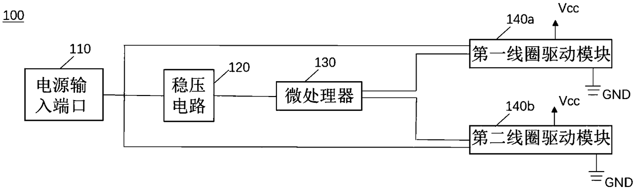
[0070] see figure 1 , figure 1 It is a schematic block diagram of a wireless charging system (hereinafter referred to as "wireless charging system") provided by Embodiment 1 of the present invention. The wireless charging system 100 includes a power input port 110 , a voltage stabilizing circuit 120 , a microprocessor 130 , a first coil driving module 140 a and a second coil driving module 140 b. Wherein, the power input port 110, the voltage stabilizing circuit 120, the microprocessor 130, the first coil driving module 140a and the second coil driving module 140b can be arranged in the same integrated circuit.

[0071] The voltage stabilizing circuit 120 is electrically connected to the power input port 110 and the microprocessor 130 . For example, the power input port 110 can be a USB port, a micro USB port or a C-type port. The voltage stabilizing circuit 120 stabilizes the voltage of the power signal input from the power input port 110 . The microprocessor 130 receives...

Embodiment 2

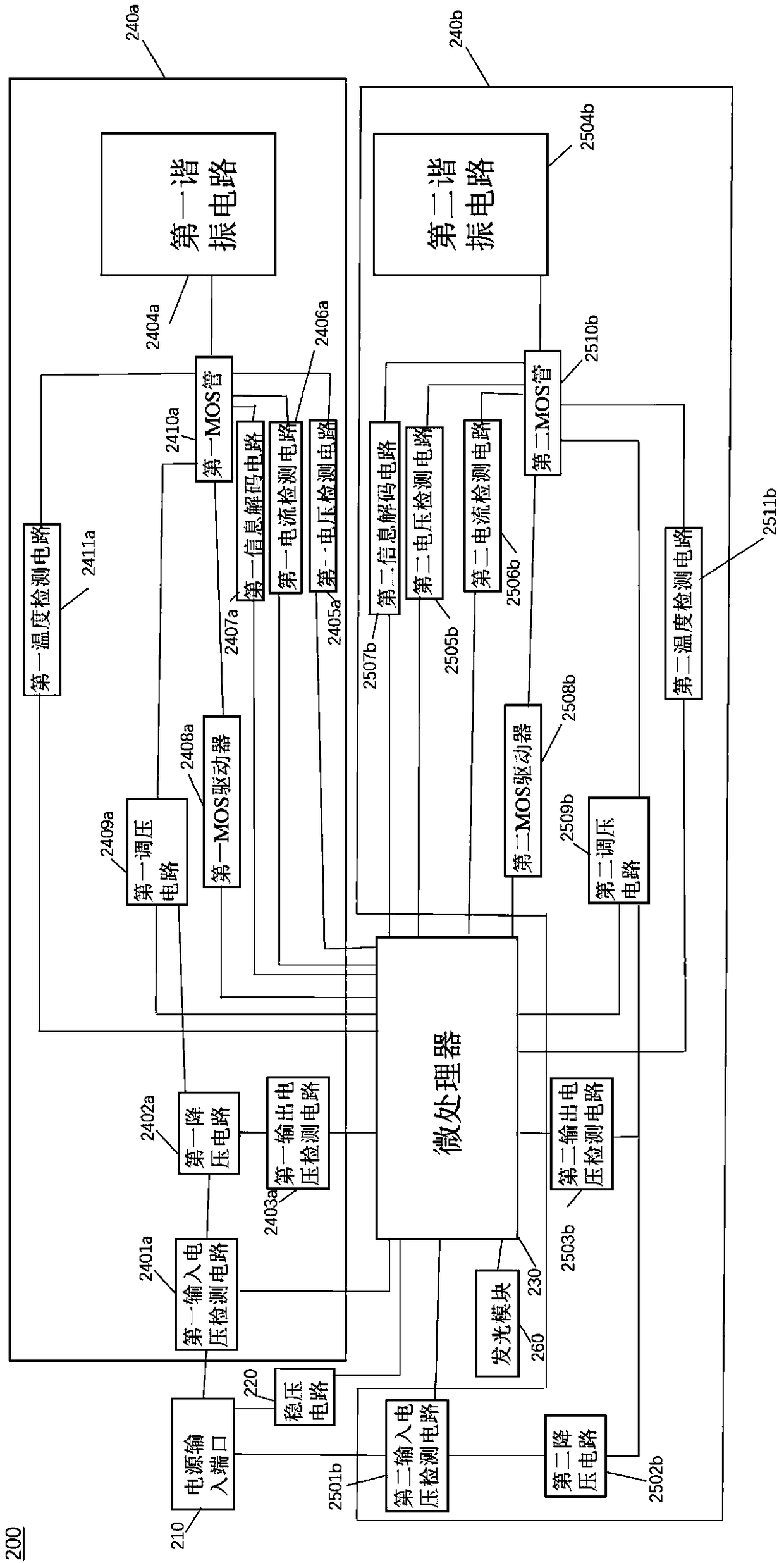
[0077] see figure 2 , figure 2 It is a schematic block diagram of a wireless charging system (hereinafter referred to as "wireless charging system") provided by Embodiment 2 of the present invention. The wireless charging system 200 includes a power input port 210 , a voltage stabilizing circuit 220 , a microprocessor 230 , a first coil driving module 240 a , a second coil driving module 240 b and a light emitting module 260 .

[0078] The first coil driving module 240a includes a first input voltage detection circuit 2401a, a first step-down circuit 2402a, a first output voltage detection circuit 2403a, a first resonance circuit 2404a, a first voltage detection circuit 2405a, a first current detection circuit 2406a, The first information decoding circuit 2407a, the first MOS driver 2408a, the first voltage regulation module 2409a, the first MOS transistor 2410a and the first temperature detection circuit 2411a.

[0079] The second coil drive module 240b includes a second ...

Embodiment 3

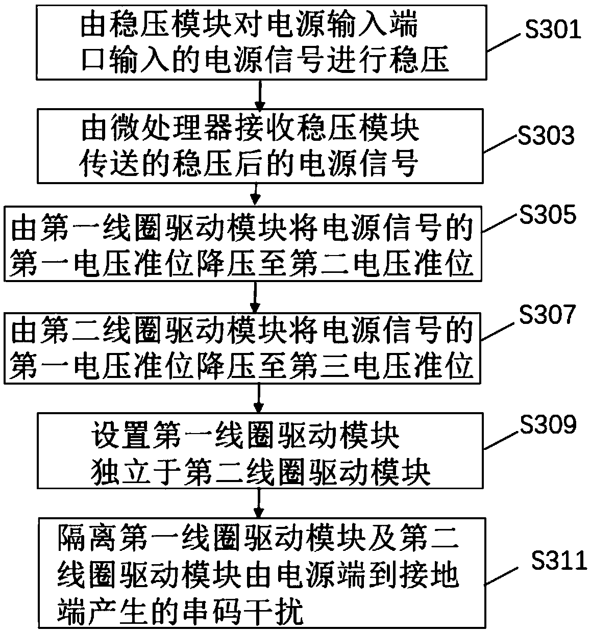
[0101] see image 3 , image 3 It is a flow chart of a method for providing a multi-coil wireless charging method (hereinafter referred to as "wireless charging method") in Embodiment 3 of the present invention. Wireless charging methods include:

[0102] S301. Stabilize the voltage of the power signal input from the power input port by the voltage stabilizing circuit;

[0103] S303. The microprocessor receives the regulated power signal transmitted by the voltage stabilizing circuit;

[0104] S305. Step down the first voltage level of the power signal to the second voltage level by the first coil driving module;

[0105] S307. Step down the first voltage level of the power signal to the third voltage level by the second coil driving module;

[0106] S309, setting the first coil driving module to be independent from the second coil driving module;

[0107] S311. Isolate the serial code interference generated from the power terminal to the ground terminal of the first coil...


PUM


Abstract

The invention provides a multi-coil wireless charging system, comprising a power input port, a voltage stabilizing circuit, a microprocessor, a first coil driving module and a second coil driving module. The voltage stabilizing circuit is electrically connected to the power input port. The voltage regulating circuit regulates the voltage of the power supply signal input from the power input port.The first and second coil driving module are electrically connected with the microprocessor and the power input port respectively. The first coil driving module reduces the first voltage level of thepower supply signal to the second voltage level. The second coil drive module reduces the first voltage level of the power supply signal to the third voltage level. The first coil driving module is independent of the second coil driving module, and is used for isolating the string code interference generated by the first coil driving module and the second coil driving module from the power terminal to the ground terminal. The wireless charging system provided by the invention effectively prevents the string code interference between the first coil driving module and the second coil driving module.

Description

technical field [0001] The invention relates to the field of electronic circuits, in particular to a multi-coil wireless charging system and method. Background technique [0002] Generally speaking, one wireless charging transmitter can only charge one wireless charging receiver. In the prior art, when a wireless charging transmitter charges multiple wireless charging receivers, multiple circuit modules connected in parallel are used. The disadvantage of this method is that the signals interfere with each other, and more power input terminals need to be laid And the adapter, the cost has caused great waste, and requires too many wire harnesses, resulting in inconvenient use. Contents of the invention [0003] In view of the above problems, the present invention provides a multi-coil wireless charging system, which can effectively solve signal mutual interference. [0004] In order to achieve the above object, the present invention adopts the following technical solutions...

Claims


Application Information

Patent Timeline
IPC IPC(8): H02J50/40H02J50/12
CPCH02J50/12H02J50/40
Inventor 曾有根杨小强
Owner SHENZHEN FANG XIN TECH
Why Eureka
Try Eureka