A DC power supply system and a control method thereof
A DC power supply system and power supply end technology, applied in current collectors, electromechanical devices, electric vehicles, etc., can solve problems such as low power conversion efficiency, achieve the effects of no high-frequency electromagnetic radiation, diversified combinations, and improved power conversion efficiency
- Summary
- Abstract
- Description
- Claims
- Application Information
AI Technical Summary
Problems solved by technology
Method used
Image

Examples
Embodiment 1
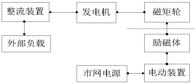
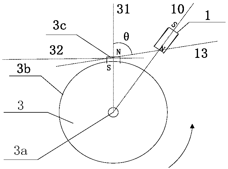
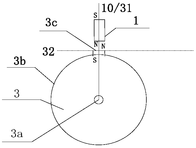
[0056]A kind of DC power supply system of the present invention comprises exciter 1, electromotive device 2, magnetic moment wheel 3, generator 4 and rectifier; Generator 4 is a conventional rotary generator, and its power supply output terminal is connected with rectifier The power supply input terminal is connected; the center of the magnetic moment wheel 3 has a hole, and the hole passes through the rotating shaft 4a of the generator 4 and is mechanically connected to it, so that the axis of the rotating shaft 3a of the magnetic moment wheel 3 coincides with the axis of the rotating shaft 4a of the generator 4 Installation effect; the outer edge of the rim 3b of the magnetic moment wheel 3 is provided with 4 rotating magnets 3c, the S pole faces the rotating shaft 3a, and the N pole faces the outer edge of the rim 3b, as Figure 4 As shown; the electric device 2 is a reciprocating motor driven by an alternating current, which includes a position sensor and a control module, ...
Embodiment 2
[0060] Carry out technical improvement on the basis of embodiment 1, two magnetic moment wheels 3 are set at the rotating shaft 4a of generator 4, and the rotating shaft 3a of two magnetic moment wheels 3 is installed on the rotating shaft 4a of generator 4 respectively; Two magnetic moment wheels 3 The distribution of the rotating magnets 3c on the rim 3b is the same, so that it can be regarded as a magnetic moment wheel 3 with respect to the longitudinal reference of the rotating shaft 4a of the generator 4; at the same time, two exciters 1 are respectively arranged corresponding to the two magnetic moment wheels 3, and the two Each exciter 1 is respectively fixedly installed on the reciprocating electric device; in the electric device 2, on the bracket corresponding to the rim 3b close to the two magnetic moment wheels 3, two position sensors are fixedly installed respectively (in order to improve the reliability of the sensor signal source sex). During installation, the N-...
Embodiment 3
[0063] The rotating shaft 3a of the magnetic moment wheel 3 of embodiment 1 is arranged coaxially with the rotating shaft 4a of the generator 4. In this embodiment, the shaft of the magnetic moment wheel 3 is set on a speed change mechanism, and the speed change mechanism is fixedly set on the generator. On the rotating shaft 4a of 4, the axle center of magnetic moment wheel 3, the axle center of speed change mechanical device, the axle center of generator 4 rotating shaft 4a coincide. In addition, the disk-shaped magnetic moment wheel 3 is composed of two rings of different materials, wherein the material of the ring 3b2 is ABS, and the material of the ring 3b1 is a non-magnetic alloy.
[0064] The configuration of other components and the working logic control method of this embodiment are the same as those described in Embodiment 1.
[0065] The rotation speed of the generator 4 in this embodiment is not limited to be the same as the rotation speed of the magnetic moment wh...
PUM
 Abstract
Description
Claims
Application Information
 - R&D
- Intellectual Property
- Life Sciences
- Materials
- Tech Scout
- Unparalleled Data Quality
- Higher Quality Content
- 60% Fewer Hallucinations
Browse by: Latest US Patents, China's latest patents, Technical Efficacy Thesaurus, Application Domain, Technology Topic, Popular Technical Reports.
© 2025 PatSnap. All rights reserved.Legal|Privacy policy|Modern Slavery Act Transparency Statement|Sitemap|About US| Contact US: help@patsnap.com