Waste and regeneration device

A technology of regeneration device and waste sand, which is applied in foundry molding equipment, machinery for cleaning/processing of casting materials, metal processing equipment, etc. The effect of shortening the time required for drying, high quality of regeneration and recovery, and improving the effect of washing

Pending Publication Date: 2018-12-18
柳晶机械设备(溧阳)有限公司
View PDF6 Cites 2 Cited by
  • Summary
  • Abstract
  • Description
  • Claims
  • Application Information

AI Technical Summary

Problems solved by technology

[0002] At present, the amount of waste sand used in the foundry industry is very large. If the traditional waste sand is used, because the waste sand is unqualified, sometimes there will be sand sticking and sand inclusions in the castings. Light and heat radiation, black soot flying, causing environmental pollution
The reuse rate of old sand is low, and the annual discharge of foundry waste sand in my country is more than 10 million tons
Due to improper treatment technology, it not only pollutes the environment, but also causes a lot of waste of resources.
[0003] When recycling and reusing foundry waste sand, it needs to be ground into fine sand particles for collection and utilization. Most of the existing waste sand treatment devices are ground by simple machines and then cleaned, so the efficiency of waste sand recovery is low, which affects work efficiency. Moreover, the waste sand treatment is not thorough, and the recycling quality is poor. It is easy to cause the recycled waste sand to fail to meet the recycling standards and cannot be reused. As a result, many foundry waste sands are discharged directly without treatment, polluting the environment, and wasting resources.

Method used


Image

  • Waste and regeneration device
  • Waste and regeneration device
  • Waste and regeneration device

Examples


Embodiment Construction

[0029] The technical solutions in the embodiments of the present invention will be clearly and completely described below in conjunction with the drawings in the present invention. Apparently, the described embodiments are only some of the embodiments of the present invention, not all of them. Based on the embodiments of the present invention, all other embodiments obtained by persons of ordinary skill in the art without making creative efforts belong to the protection scope of the present invention.

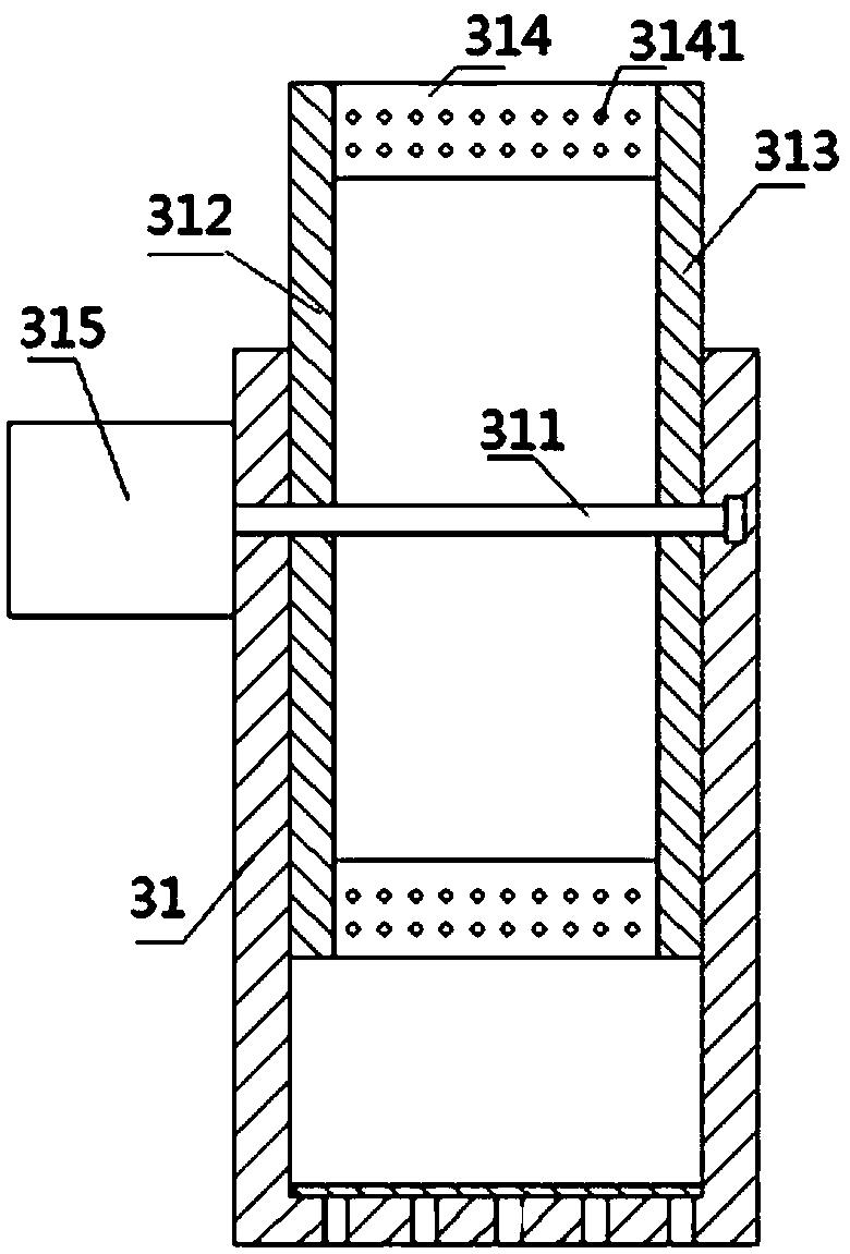
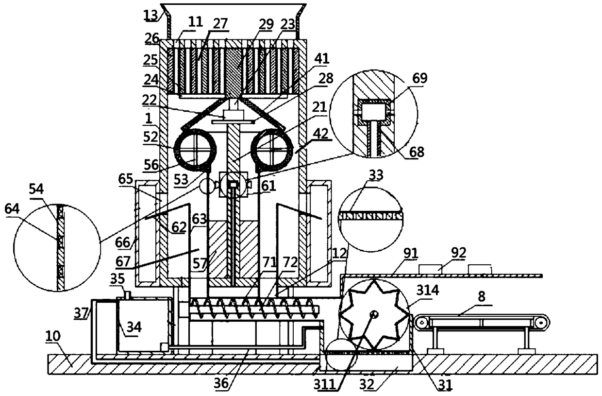
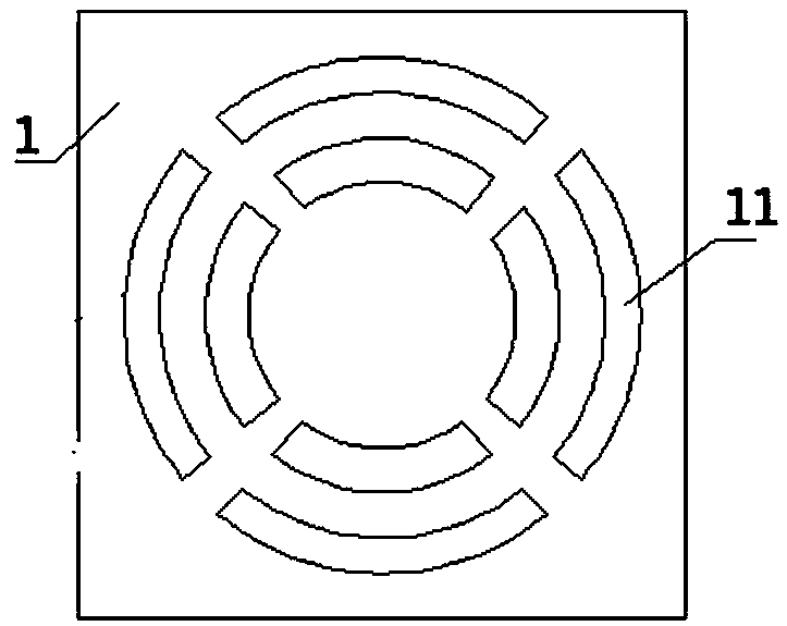
[0030] Such as Figure 1 to Figure 3 As shown, a waste sand regeneration device according to an embodiment of the present invention includes a main box 1, a grinding device, and a cleaning device, wherein: the main box 1 is a square box, and its top surface is coaxially opened with several holes from the inside to the outside. Discontinuous annular sand inlet 11, the two sides of its bottom surface are provided with sand outlet 12; Grinding device is arranged on the top of main ...


PUM


Abstract

The invention relates to the technical field of recovery of waste foundry sand, in particular to a waste sand regeneration device. The waste sand regeneration device comprises a main box, a grinding device and a cleaning device, wherein the main box is a square box, a plurality of discontinuous annular sand inlets are coaxially formed in the top surface of the main box from inside to outside, andsand outlets are formed in the two sides of the bottom surface of the main box; the grinding device is arranged at the top of the main box and comprises a supporting rod, a first driving device, a first rotary shaft, a plurality of fixed connecting rods, a plurality of first annular blocks with different diameters and a plurality of second annular blocks with different diameters, wherein the firstannular blocks are spaced from the second annular blocks; grinding gaps corresponding to the annular sand inlets are formed between the first annular blocks and the adjacent second annular blocks; and the cleaning device is arranged below the main box. According to the waste sand regeneration device, waste sand is sufficiently ground in the grinding gaps, so that impurities, rust and the like onthe surface of the waste sand are removed more sufficiently, and the waste sand recovery quality is higher.

Description

technical field [0001] The invention relates to the technical field of casting waste sand recovery, in particular to a waste sand regeneration device. Background technique [0002] At present, the amount of waste sand used in the foundry industry is very large. If the traditional waste sand is used, because the waste sand is unqualified, sometimes there will be sand sticking and sand inclusions in the castings. Light and heat radiation, black soot flying, causing environmental pollution. The recycling rate of old sand is low, and the annual discharge of foundry waste sand in my country is more than 10 million tons. Due to improper treatment technology, it not only pollutes the environment, but also causes a lot of waste of resources. [0003] When recycling and reusing foundry waste sand, it needs to be ground into fine sand particles for collection and utilization. Most of the existing waste sand treatment devices are ground by simple machines and then cleaned, so the eff...

Claims


Application Information

Patent Timeline
Patent Type & Authority Applications(China)
IPC IPC(8): B22C5/04B22C5/00B22C5/06B22C5/10
CPCB22C5/00B22C5/04B22C5/045B22C5/06B22C5/10
Inventor 任文强
Owner 柳晶机械设备(溧阳)有限公司
Why Eureka
Try Eureka