A charging pile energy storage structure power supply monitoring method

A charging pile and energy storage technology, applied in charging stations, vehicle energy storage, electric vehicle charging technology, etc., can solve the problems of normal use, the inability of charging pile units to meet the charging needs, and wasting time.

Active Publication Date: 2021-04-23
重庆国翰能源发展有限公司
View PDF25 Cites 0 Cited by
  • Summary
  • Abstract
  • Description
  • Claims
  • Application Information

AI Technical Summary

Problems solved by technology

The monitoring of the capacity or remaining power of the energy storage stack or battery is very important for the service life of the charging pile, because there is a unified correspondence between the open circuit voltage of a specific battery and its remaining power, but when in use, due to the uncertain use of the charging pile, the battery The self-discharge is uncertain, the internal resistance of the battery changes with the temperature and aging conditions, and there is a large deviation between the traditional power monitoring and the actual use. It is difficult for the user to know the capacity of the corresponding energy storage structure of the charging pile in advance. The use of multiple charging piles at the same time will affect the power consumption of the unit. There is a waste of time waiting for the charging pile unit to be unable to meet the charging demand, and setting up one or two fixed small charging piles is also not reasonably allocated to the energy storage pile to a certain extent. The electric energy has brought troubles to normal use
The current charging pile energy storage structure lacks optimal management of power usage. In order to solve this problem, it is necessary to conduct in-depth research

Method used


Image

  • A charging pile energy storage structure power supply monitoring method
  • A charging pile energy storage structure power supply monitoring method

Examples


Embodiment Construction

[0026] The technical solutions in the present utility model are further described below with reference to the accompanying drawings and embodiments.

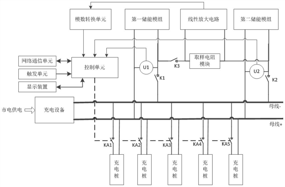
[0027] A method for monitoring power supply of a charging pile energy storage structure, comprising the following steps:

[0028] A. Set up the first energy storage module and the second energy storage module that can independently supply power to the charging pile; during the period of supplying power from the mains, the first energy storage module and the second energy storage module are powered by the charging pile at the same time. A power supply connection to the charging pile;

[0029] B. Record the parameter data and unit charging data of the first energy storage module and the second energy storage module; the parameter data includes discrete data SOC of the battery capacity corresponding to the open circuit voltage of several batteries, and the residual voltage EV of the safe depth of discharge; The unit charging data ...


PUM


Abstract

The present invention provides a charging pile energy storage structure power supply monitoring method. The energy storage stack is set as two energy storage units, the first energy storage module and the second energy storage module, which helps the two energy storage units to store differences The amount of electricity can be transferred from a relatively high-energy energy storage unit to a relatively low-energy energy storage unit, and the open circuit voltage and terminal voltage of the energy storage unit can be obtained, as well as the current formed by the charge transfer between the energy storage units, and the energy storage unit can be calculated. The internal resistance of the energy storage unit; the control unit obtains the current of the transferred power between the two energy storage units through the sampling voltage and the resistance value of the sampling resistance module, and calculates the internal resistance of the energy storage unit through the current, so that it can be obtained according to the charging data of the unit, etc. Effective voltage, combined with the stored unit charging data, safe discharge depth, remaining power EV and other parameter data to calculate the safe charging times, and compare it with the number of charging piles to obtain the maximum number of charging piles that can be used normally, and realize the optimization of the charging pile energy storage structure usage management.

Description

technical field [0001] The invention relates to the technical field of charging piles, in particular to the application field of energy storage control of charging piles. Background technique [0002] At present, the power supply terminals of each charging pile of the charging station are connected in parallel with the bus terminal, and the bus terminal is connected to the power input. In order to ensure the energy storage capacity, a plurality of batteries are connected in series and parallel to form an energy storage stack, and the whole is connected in parallel with the bus terminal. The monitoring of the capacity or remaining power of the energy storage stack or battery is very important for the use time of the charging pile. Since there is a unified correspondence between the open circuit voltage of a specific battery and its remaining power, but during use, due to the uncertainty of the use of the charging pile, the battery The self-discharge is uncertain, the interna...

Claims


Application Information

Patent Timeline
Patent Type & Authority Patents(China)
IPC IPC(8): B60L53/60B60L53/67B60L53/68
CPCY02T10/70Y02T10/7072Y02T90/12Y02T90/16
Inventor 刘崇汉李杰
Owner 重庆国翰能源发展有限公司
Why Eureka
Try Eureka