A system for automatically identify a tractor trailer and a control method thereof

A technology of automatic identification and control methods, applied in the direction of signal devices, etc., to achieve the effect of intelligent judgment, simple structure design, and high judgment reliability

Active Publication Date: 2018-12-18
DONGFENG COMML VEHICLE CO LTD
View PDF8 Cites 7 Cited by
  • Summary
  • Abstract
  • Description
  • Claims
  • Application Information

AI Technical Summary

Problems solved by technology

[0005] The purpose of the present invention is to overcome the problem in the prior art that the trailer switch needs to be used to confirm the hanging state, and to provide a system for automatically identifying the tractor trailer without a trailer switch and its control method

Method used


Image

  • A system for automatically identify a tractor trailer and a control method thereof

Examples


Embodiment 1

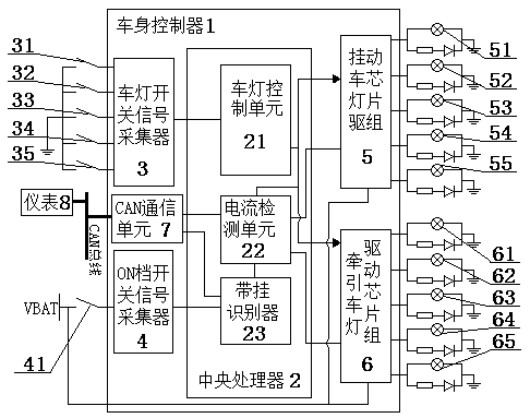
[0056] An automatic identification tractor trailer system, including a body controller 1, a central processing unit 2 is provided in the body controller 1, and the body controller 1 further includes: a light switch signal collector 3, an ON gear switch signal Collector 4, trailer light driving chipset 5 and tractor light driving chipset 6, the signal output ends of the light switch signal collector 3 and the ON gear switch signal collector 4 are all connected to the signal input of the central processing unit 2. The drive signal output end of the central processing unit 2 is connected to the control end of the trailer light drive chip set 5 and the tractor light drive chip set 6 respectively, and the trailer light drive chip set 5 and the tractor The current signal feedback end of the lamp driving chipset 6 is connected to the feedback signal input end of the central processing unit 2; the signal output end of the central processing unit 2 is connected to the CAN communication u...

Embodiment 2

[0058] Embodiment 2 is basically the same as embodiment 1, and the difference lies in:

[0059] The central processing unit 2 includes a vehicle light control unit 21, a current detection unit 22, and a belt-mounted identifier 23. The signal output terminal of the vehicle light switch signal collector 3 is connected to the signal input terminal of the vehicle light control unit 21 The signal output terminals of the vehicle light control unit 21 are respectively connected to the signal input terminals of the current detection unit 22, the trailer light driving chip group 5, and the tractor light driving chip group 6, and the trailer light driving chip group 5 And the current signal feedback terminal of the traction lamp driving chip set 6 are connected to the feedback current input terminal of the current detection unit 22, the fault signal output terminal of the current detection unit 22 is connected to the CAN communication unit 7, and the current detection The trailer counting ...

Embodiment 3

[0067] Embodiment 3 is basically the same as embodiment 2, and the difference lies in:

[0068] A control method for automatically identifying the trailer system of a tractor, the second step further includes: lamp fault diagnosis, the current detection unit 22 detects the driving current of the corresponding tractor lamp, and when it is detected that the output power of the tractor lamp is zero When it is judged that the traction lamp is in an open circuit state, the current detection unit 22 sends a fault code to the meter 8 through the CAN bus; when it is detected that the output power of the traction lamp is greater than the normal power range of the traction lamp, the traction lamp is judged The vehicle light is in a short-circuit state, and the current detection unit 22 sends a fault code to the meter 8 through the CAN bus;

[0069] The current detection unit 22 detects the driving current of the corresponding trailer light, and when it detects that the output power of the tr...


PUM


Abstract

A system for automatically identify a tractor trailer includes a body controller and a central processor arranged therein, Lamp Switch Signal Collector, ON switch signal collector, a trailer lamp drive chipset and a tractor lamp drive chipset, the signal output end of the lamp switch signal collector and the ON switch signal collector are connected with the signal input end of the central processing unit, The driving signal output end of the CPU is respectively connected with the control end of the trailer lamp driving chip set and the tractor lamp driving chip set, and the current signal feedback ends of the trailer lamp driving chip set and the tractor lamp driving chip set are both connected with the feedback signal input end of the CPU, and the current signal feedback ends of the trailer lamp driving chip set and the tractor lamp driving chip set are connected with the feedback signal input end of the CPU. The signal output terminal of the central processor is connected with a CANcommunication unit, and the CAN communication unit is connected with a meter signal through a CAN bus. This design not only simplifies the structure of vehicle body and wiring harness, but also can diagnose the malfunction of vehicle lamp and judge the state of trailer.

Description

Technical field [0001] The invention relates to an automatic identification tractor trailer system and a control method thereof, and is particularly suitable for simplifying trailer control lines and realizing trailer lamp failure detection. Background technique [0002] Trailer refers to a vehicle that is towed by the main vehicle and has no power driving device. It is an important vehicle type for road transportation and can easily achieve section transportation. Trailer tail lights usually consist of position lights, reversing lights, rear fog lights, brake lights, and turn lights, and are controlled by the main vehicle. Trailer identification and trailer lights control generally use a separate trailer identification switch or trigger device to enable the main vehicle to detect and confirm the trailer status. [0003] The Chinese patent publication number is CN101296810A, and the publication date is October 29, 2008. The invention patent discloses a sensor device for detecting ...

Claims


Application Information

Patent Timeline
Patent Type & Authority Applications(China)
IPC IPC(8): B60Q11/00
CPCB60Q11/005B60Q11/007
Inventor 代鹏刘双平申培锋鲁欢王高举熊江涛
Owner DONGFENG COMML VEHICLE CO LTD
Why Eureka
Try Eureka