Cabinet stacking machine with anti-tilting device

A stacker and anti-dumping technology, applied in the field of stackers, can solve the problems of large cabinet size, complex mechanical structure, and small storage quantity, and achieve the effect of good anti-dumping effect, simple mechanical structure and high degree of automation.

Pending Publication Date: 2018-12-18
江苏博睿通智能装备有限公司
View PDF0 Cites 3 Cited by
  • Summary
  • Abstract
  • Description
  • Claims
  • Application Information

AI Technical Summary

Problems solved by technology

[0002] At present, due to the thin and tall shape of the switchgear, its size is generally length: 600-1000mm×width: 600-1000mm×height: 2200-2400mm, so its storage mode is single-layer ground storage, and the way in and out of the warehouse is uniform. For forklifts or mobile cranes, the workshop occupies a large area, the storage quantity is small, and the warehouse management efficiency is low
Therefore, an automatic three-dimensional high-bay warehouse has been developed on the market. It is stored in multiple layers. It is very easy to dump due to the high center of gravity on the stacker loading platform. The existing solid loading platform uses electric screw rods for clamping. The mechanism clamps the cabinet body, but the mechanical structure is complicated, the electrical control is complicated, and the cabinet body size is large. Once the cabinet body is put into storage, the position is a bit shifted, not in the center of the loading platform, and the cabinet body is easy to be clamped. Even Cause cabinet deformation

Method used


Image

  • Cabinet stacking machine with anti-tilting device
  • Cabinet stacking machine with anti-tilting device
  • Cabinet stacking machine with anti-tilting device

Examples


Embodiment 1

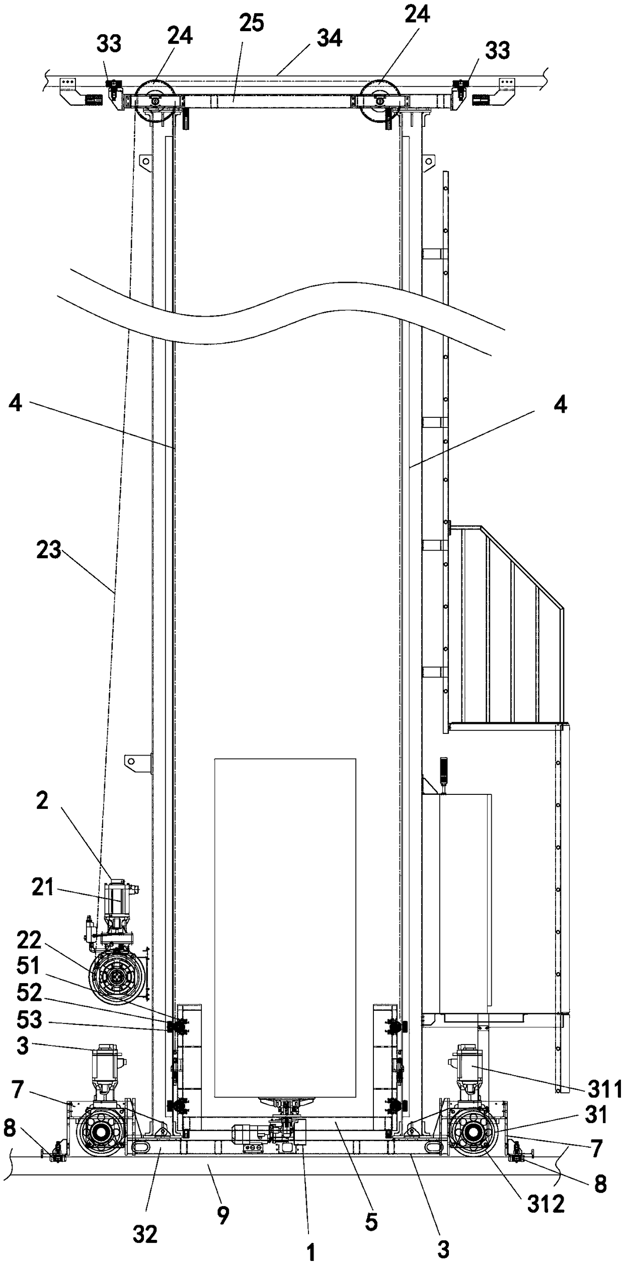
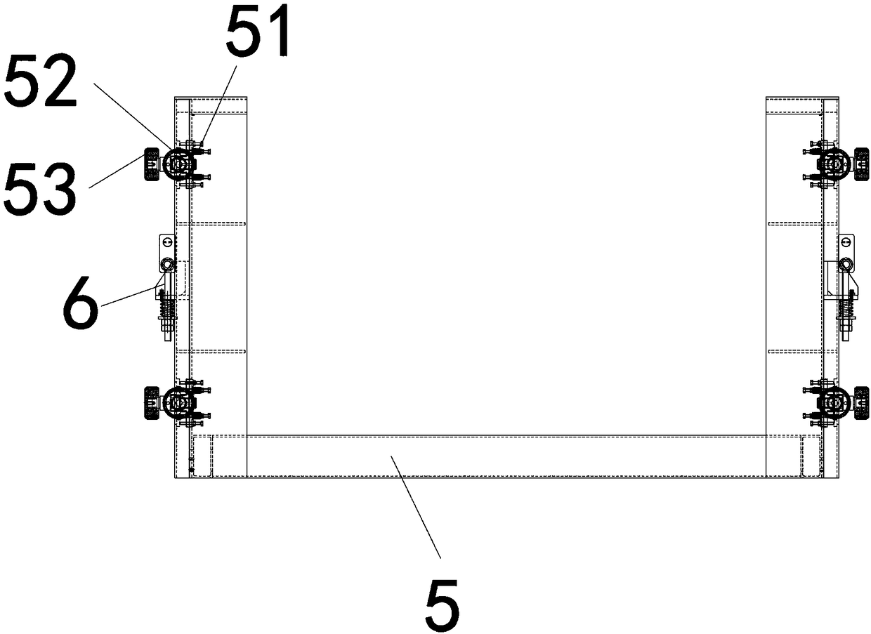
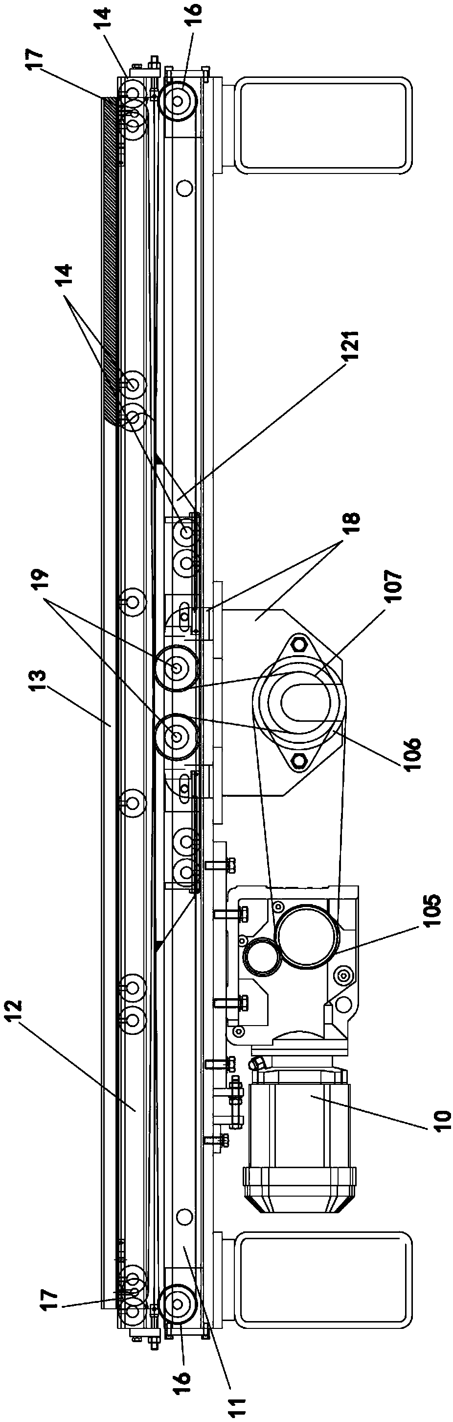
[0027] Such as Figure 1-Figure 9 As shown, a cabinet stacker with an anti-dumping device described in this embodiment includes a lifting mechanism 2, a lateral displacement mechanism 3, a loading platform 5, two columns 4 and a switch cabinet for automatic picking and placing. The telescopic cargo fork 1; the loading platform 5 is located between the two uprights 4, and the positioning rollers 53 on both sides of the loading platform 5 are located in the guide grooves of the uprights 4; the two uprights 4 are fixed on the lateral displacement mechanism 3, and the telescopic cargo The fork 1 is installed on the cargo platform 5, and a plurality of electromagnetic devices 205 are installed on the automatic pick-and-place platform 13 of the telescopic cargo fork 1; Fixed connection. Rolling wheels 52 are installed on both sides of the loading platform 5 through a spring frame 51 , and the rolling wheels 52 are attached to the inner side walls of the columns 4 .

[0028] The de...


PUM


Abstract

The invention discloses a cabinet stacking machine with an anti-tilting device. The cabinet stacking machine with the anti-tilting device comprises a lifting mechanism, a horizontal displacement mechanism, a loading table, two stand columns, and a telescopic fork for automatically picking and placing a switch cabinet, wherein the loading table is located between the two stand columns; positioningrollers on two side parts of the loading table are located in guiding grooves of the stand columns; the two stand columns are fixed onto the horizontal displacement mechanism; the telescopic fork is arranged on the loading table; multiple electromagnetic devices are arranged on an automatic picking and placing platform of the telescopic fork; the lifting mechanism is arranged on one stand column;and a lifting part of the lifting mechanism is fixedly connected with the loading table. The cabinet stacking machine with the anti-tilting device is simple in mechanical structure, small in size, lowin cost, simple and easy to control, and good in anti-tilting effect; the automation degree is high, and the operation of manual carrying and feeding is omitted, so that the accuracy, the stability and the safety performance of feeding are improved, and the equipment cost of an electric cabinet assembly line is reduced; and even if a cabinet body is placed fixedly but shifts, the occurrence of the phenomenon of deformation of a cabinet body is avoided.

Description

technical field [0001] The invention relates to the technical field of a stacker, in particular to a cabinet stacker with an anti-dumping device. Background technique [0002] At present, due to the thin and tall shape of the switchgear, its size is generally length: 600-1000mm×width: 600-1000mm×height: 2200-2400mm, so its storage mode is single-layer ground storage, and the way in and out of the warehouse is uniform. For forklifts or mobile cranes, the workshop occupies a large area, the storage quantity is small, and the warehouse management efficiency is low. Therefore, an automatic three-dimensional high-bay warehouse has been developed on the market. It is stored in multiple layers. It is very easy to dump due to the high center of gravity on the stacker loading platform. The existing solid loading platform uses electric screw rods for clamping. The mechanism clamps the cabinet body, but the mechanical structure is complicated, the electrical control is complicated, an...

Claims


Application Information

Patent Timeline
Patent Type & Authority Applications(China)
IPC IPC(8): B66F9/07B66F9/075B66F9/12B66F9/24
CPCB66F9/07B66F9/0755B66F9/12B66F9/24
Inventor 鞠文彬胡贤清宋智强
Owner 江苏博睿通智能装备有限公司
Why Eureka
Try Eureka