Magnetic resin water purification equipment

A technology of magnetic resin and water purification equipment, applied in water/sewage treatment, adsorption water/sewage treatment, water/sludge/sewage treatment, etc. The problems of large investment in stirring paddles can improve the service life, better exchange and adsorption effect, and reduce investment costs and maintenance costs.

Pending Publication Date: 2018-12-18
江苏神洲环境工程有限公司
View PDF0 Cites 0 Cited by
  • Summary
  • Abstract
  • Description
  • Claims
  • Application Information

AI Technical Summary

Problems solved by technology

[0003] 1. At present, most of the similar water purification equipment at home and abroad adopt the type of mechanical stirring paddle built in the center of the equipment after adding magnetic resin: First, the investment of mechanical stirring paddle is large and the energy consumption is high
Second, it is not conducive to the normal maintenance and maintenance of the equipment. Once the stirring paddle fails, it will cause production stoppage.
3. As the rotation of the mechanical stirring paddle promotes the stirring and mixing of the raw water and the magnetic resin, it is inevitable that the paddle and the magnetic resin particles will repeatedly collide with each other in a large area, which greatly increases the damage rate of the magnetic resin and seriously reduces the magnetic resin during operation. service life
[0004] 2. The return flow of active sludge in the original clarifier is controlled by moving the throat up and down to adjust the distance between the nozzle and the throat to adjust the size of the return flow. The overall throat is large and heavy, and it is very inconvenient to move up and down.

Method used


Image

  • Magnetic resin water purification equipment

Examples


Embodiment Construction

[0020] The present invention will be further explained below in conjunction with the accompanying drawings.

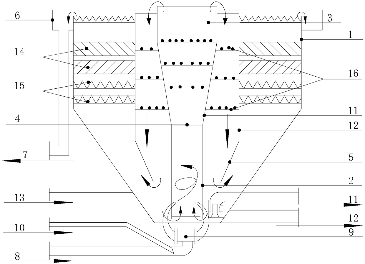
[0021] The invention discloses a magnetic resin water purification device, which comprises a large cylinder body 1, an exchange cylinder body 2 is arranged below the large cylinder body 1, an exchange cylinder body chamber 3 is arranged above the exchange cylinder body 2, and an exchange cylinder body chamber 3 is covered with an exchange The second chamber 4 of the cylinder body, the lower end of the second chamber 4 of the exchange cylinder body is provided with an anti-skirt plate 5 at the lower opening of the second chamber; the large cylinder body 1 is divided into a separation area and a clean water area; the top of the large cylinder body 1 is provided with a water collection tank 6; There is a water outlet pipe 7, which communicates with the water collection tank 6; the bottom of the large cylinder 1 is provided with a water inlet pipe 8, and the water inlet pip...


PUM


Abstract

The invention discloses magnetic resin water purification equipment, which comprises a big tube body, wherein an exchange tube body is arranged under the big tube body; anfirstexchange tube body firstchamber is arranged above the exchange tube body; ansecond exchange tube body second chamber covers outside the first exchange tube body first chamber; a second chamber lower opening reverse skirt plate is arranged at the lower end of the second exchange tube secondbody chamber; the big tube body is divided into a separation region and a clean water region; a water collecting groove is arranged on the top of the big tube body; a water outlet pipe is arranged at the outer side of the big tube body; the water outlet pipe is communicated with the water collecting groove; a water inlet pipe is arranged at the bottom of the big tube body; the water inlet pipe is communicated with the exchange tube body through a cow head double-horn type spray nozzle assembly and the exchange tube body; a magnetic resin adding pipe is arranged on the water inlet pipe; a magnetic resin catching device is arranged under the big tube body; the bottom end of the big tube body is provided with an overhaul exhaust pipe; a magnetic resin unplugging device is arranged under the big tube body; the upper end of the exchange tube body first chamber is communicated with the lower end of the firstexchange tube bodyfirst chamber; the upper end of the first exchange tube body first chamber is communicated with the upper end of the second exchange tube bodysecond chamber. The magnetic resin water purification equipment disclosed by the invention has the advantages that the structure is simple;, the exchange effect is good;, the operation cost is lowandavoids the complex and inefficientstructuresexisting in the prior art.

Description

technical field [0001] The invention relates to sewage treatment equipment, in particular to magnetic resin water purification equipment. Background technique [0002] The current domestic similar water purification equipment is properly improved on the basis of the introduction and digestion of similar foreign water purification equipment, but there are also certain deficiencies and shortcomings. [0003] 1. At present, most of the similar water purification equipment at home and abroad adopt the type of mechanical stirring paddle built in the center of the equipment after adding magnetic resin: First, the investment of mechanical stirring paddle is large and the energy consumption is high. The second is that it is not conducive to the normal maintenance and maintenance of the equipment. Once the stirring paddle breaks down, it will cause production stoppage. 3. As the rotation of the mechanical stirring paddle promotes the stirring and mixing of the raw water and the magn...

Claims


Application Information

Patent Timeline
Patent Type & Authority Applications(China)
IPC IPC(8): C02F1/28
CPCC02F1/285
Inventor 陈瑶王籽涵
Owner 江苏神洲环境工程有限公司
Why Eureka
Try Eureka