Manufacturing method of crack-free laser cladding amorphous coating

A laser cladding and amorphous coating technology, applied in the field of materials, can solve the problems of high requirements on energy conditions and equipment types, unfavorable industrialization advancement, loss of strength of cladding layers, etc. The effect of preparing production efficiency and improving microstructure

Active Publication Date: 2018-12-18
ARMOR ACADEMY OF CHINESE PEOPLES LIBERATION ARMY
View PDF7 Cites 6 Cited by
  • Summary
  • Abstract
  • Description
  • Claims
  • Application Information

AI Technical Summary

Problems solved by technology

Traditionally, there are two methods to solve the crack problem, that is, optimizing the cladding material and adjusting the preparation process. However, the current crack removal process mainly has the following problems: 1) In terms of material performance, it is important to improve toughness and reduce crack sensitivity. At the same time, the strength loss of the cladding layer is serious; 2) In the material system, the method of adding rare refractory metals, rare earth elements or hard reinforcing phases is used to prepare the crack-free cladding layer, which is expensive and the prepared The amorphous content of the cladding layer is very low, which cannot meet the new requirements for high performance of new products in the new stage; 3) In terms of process parameters, traditional methods generally require high power input when removing cracks, and have relatively high requirements for energy conditions and equipment types. High, not conducive to energy saving and emission reduction, and not conducive to large-scale promotion and use; 4) In terms of process flow, the operation process is cumbersome and strict when using preheating means to heat the substrate or slow cooling after cladding, resulting in low work efficiency and serious energy consumption , is not conducive to the promotion of industrialization

Method used


Image

  • Manufacturing method of crack-free laser cladding amorphous coating
  • Manufacturing method of crack-free laser cladding amorphous coating
  • Manufacturing method of crack-free laser cladding amorphous coating

Examples


Embodiment 1

[0032] Embodiment 1 The screening of the first preset process (pre-melting step) parameters

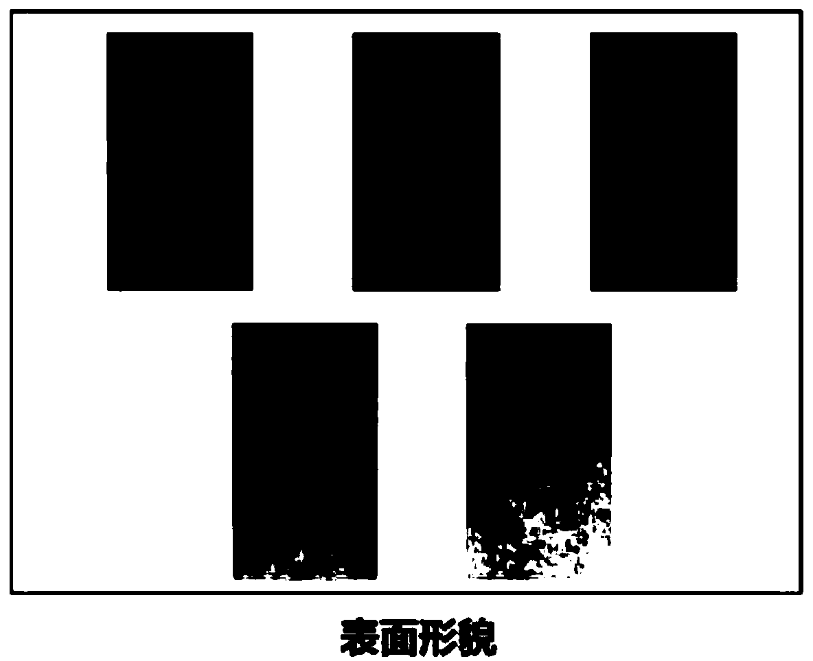
[0033] Select block 45# steel of 140(mm)×100(mm)×8(mm) as the substrate, use the first preset process parameters (a: 4mm / s+0.5kW) and other process parameters (b: 2mm / s+0.5kW, c:4mm / s+0.8kW, d:4mm / s+0.3kW, e:7mm / s+0.5kW) for pre-melting. The laser focus spot size is 14mm×1.5mm, and the protective argon flow rate is 20L / min.

[0034] The substrate surface morphology after the pre-melting of embodiment 1 is as follows figure 1 shown. Among them, the pre-melting parameters are a: 4mm / s-0.5kW, b: 2mm / s-0.5kW, c: 4mm / s-0.8kW, d: 4mm / s-0.3kW and e: 6mm / s-0.5 kW. It can be seen that the matrix premelted with the first premelting parameters ( figure 1 In a) there is no obvious burning trace on the surface, while the substrate under parameter b is burnt to dark black ( figure 1 In b), the substrate is burnt to beige ( figure 1 In c), this is the result of local overheating of the subst...

Embodiment 2

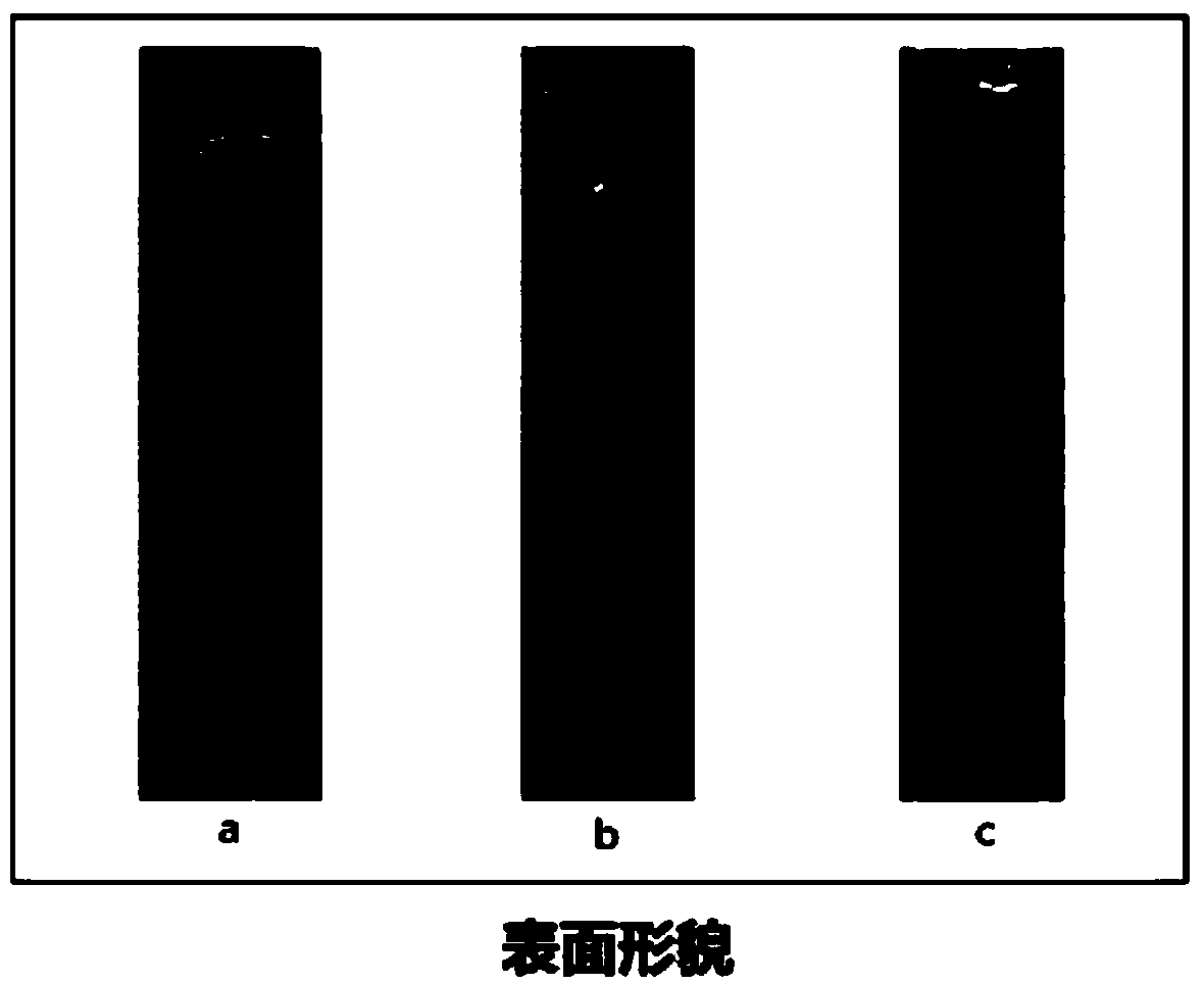
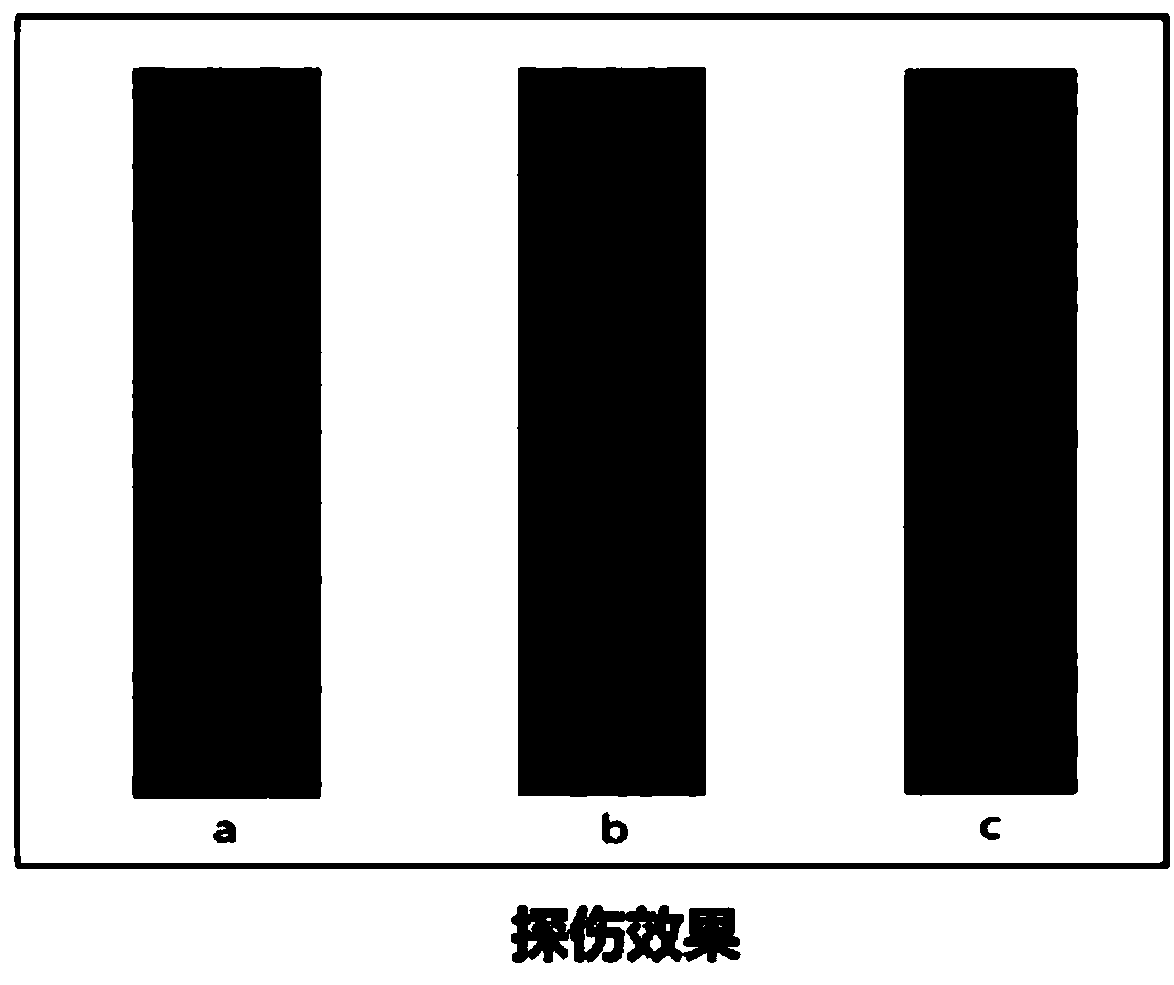
[0040] Take six kinds of raw metal powders according to mass percentage: 18.00% Co, 18.00% Ni, 4.00% B, 2.00% Si, 4.00% Nb, and the balance is Fe, and carry out weighing batching. And placed in a powder mixer and mixed for 10h. After the powders were mixed, they were dried in vacuum at low temperature for 3 hours, and a cladding layer was prepared on the pre-melted substrate with a size of 140(mm)×100(mm)×8(mm) according to the method of Example 1. The parameters of each step are, (1) pre-melting parameters: 4mm / s-0.5kW, protective argon flow rate is 20L / min; (2) cladding parameters: 5mm / s-2.0kW, protective argon flow rate is 15L / min; (3) The remelting parameters are: 5mm / s-1.5kW, the protective argon flow rate is 25L / min; the laser focus spot size is 14mm×1.5mm. Wherein, the single-pass cladding layer only carries out step (2), the remelting cladding layer only carries out steps (2) and (3), and the laser cladding amorphous coating prepared by the method of the present inven...

Embodiment 3

[0043] Take six kinds of raw metal powders according to mass percentage: 20.00% Co, 20.00% Ni, 4.00% B, 2.00% Si, 4.00% Nb, and the balance is Fe, and carry out weighing batching. And placed in a powder mixer and mixed for 10h. After the powders were mixed, they were vacuum dried at low temperature for 3 hours, and a cladding layer was prepared on a substrate with a size of 140(mm)×100(mm)×8(mm) by referring to the method of Example 1. The parameters of each step are, (1) pre-melting parameters: 4mm / s-0.5kW, protective argon flow rate is 20L / min; (2) cladding parameters: 5mm / s-2.0kW, protective argon flow rate is 15L / min; (3) The remelting parameters are: 5mm / s-1.5kW, the protective argon flow rate is 25L / min; the laser focus spot size is 14mm×1.5mm. Wherein, the single-pass cladding layer only carries out step (2), the remelting cladding layer only carries out steps (2) and (3), and the laser cladding amorphous coating prepared by the method of the present invention carries ...


PUM

PropertyMeasurementUnit
particle sizeaaaaaaaaaa
Vickers hardnessaaaaaaaaaa

Abstract

The invention provides a manufacturing method of a crack-free laser cladding amorphous coating. The manufacturing method comprises the following steps that (1) a matrix is molten in advance accordingto first preset technological parameters and is kept at the first preset temperature; (2) a coating material is arranged on the surface of the alloy matrix in a laser cladding mode according to secondpreset technological parameters, so that a cladding layer is formed; and (3) after the surface temperature of the cladding layer is reduced to be equal to the first preset temperature, the alloy matrix which is subjected to cladding is molten again according to third preset technological parameters and is cooled. By the adoption of the manufacturing method, the laser cladding amorphous coating which is completely free of cracks can be manufactured, the crack condition is improved, the amorphous content and the microhardness of the laser cladding layer can also be increased, the amorphous content in the laser cladding amorphous coating is larger than 40%, and the average micro vickers hardness is 807.4HV0.1. The manufacturing method is low in cost, all the technological processes can be accomplished on one laser cladding facility, and therefore operation can be easier, manufacture can be more efficient, and the application range can be broader.

Description

technical field [0001] The invention relates to the field of material technology, in particular to a method for preparing a crack-free laser cladding layer. Background technique [0002] my country is a big manufacturing country. The implementation of the "Belt and Road" policy has accelerated the advancement of China's strategic construction of "manufacturing power" and "innovative country", and the requirements for the domestic steel industry have been continuously upgraded. The roll is the core component of the rolling mill, which can roll various metal materials into products. The innovation and upgrading of metal products have more and more stringent requirements on the working conditions of the rolls. The interaction of factors such as cold, heat, high speed, and heavy loads makes the rolls prone to damage and failure behaviors such as roll surface fatigue peeling, wear, and roll body fracture. Relevant data show that the annual scrapping of hot and cold rolls and bac...

Claims


Application Information

Patent Timeline
Patent Type & Authority Applications(China)
IPC IPC(8): C23C24/10
CPCC23C24/106
Inventor 蔡志海程江波孙博柳建刘军杜晓坤梁秀兵孙晓峰李占明郭杰
Owner ARMOR ACADEMY OF CHINESE PEOPLES LIBERATION ARMY
Why Eureka
Try Eureka