A kind of electroplating device and method of pcb circuit board

A technology for circuit boards and electrolytic cells, which is used in plating tanks, electrodes, electrolytic components, etc. to achieve the effect of improving convection speed and accelerating the balance of concentration.

Active Publication Date: 2019-11-12
惠州市联达金电子有限公司
View PDF6 Cites 0 Cited by
  • Summary
  • Abstract
  • Description
  • Claims
  • Application Information

AI Technical Summary

Problems solved by technology

The equipment is only overflow water washing, and does not involve the plating tank structure design of the electrolytic tank depositing metal

Method used


Image

  • A kind of electroplating device and method of pcb circuit board
  • A kind of electroplating device and method of pcb circuit board
  • A kind of electroplating device and method of pcb circuit board

Examples


Embodiment 1

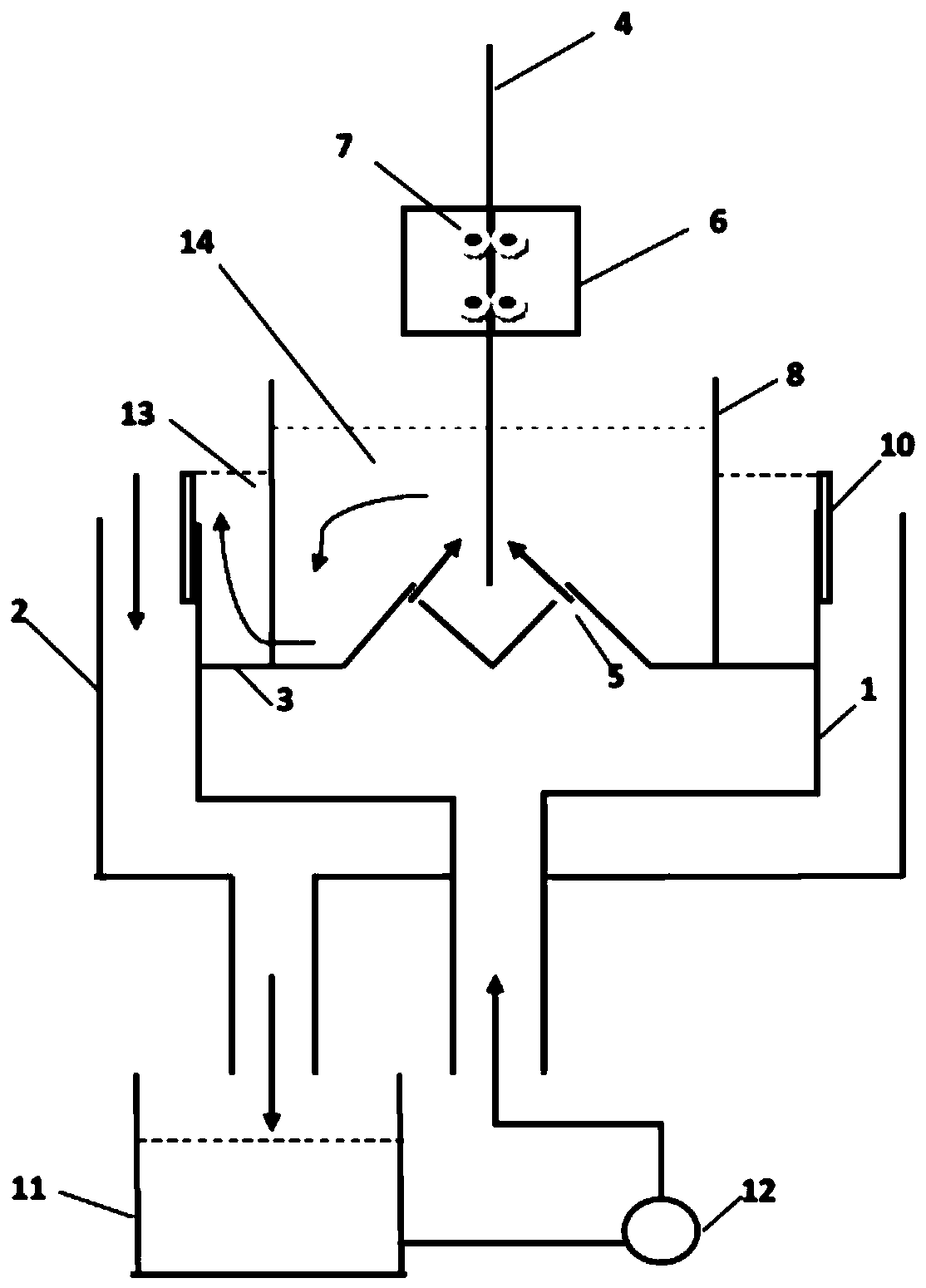
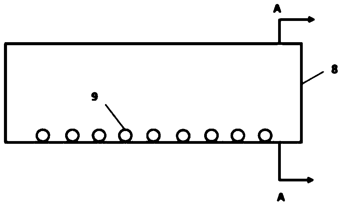
[0034] A circuit board electroplating method in which the electrolyte is forced to circulate. The electrolyte in the electrolyte storage tank 11 is pumped into the lower space of the electrolytic tank 1 through the circulation pump 12, and the tapered hole on the separator 3 provided in the middle of the electrolytic tank 1 5 is sprayed out (the angle between the outlet of the tapered hole 5 and the circuit board 4 is 45°), and the electrolyte meets the resistance of the circuit board 4 and turns back down to flow through the guide hole 9 under the anode plate 8 , flows into the electrolyte outer tank 13 formed between the anode plate 8 and the baffle plate 10, further crosses the baffle plate 10 arranged on the outer wall of the electrolytic tank 1 (outer tank 13) and flows into the overflow tank 2, and flows into the storage tank from the overflow tank Liquid tank 11, by sliding baffle plate, makes the liquid level of electrolyte outer tank 13 be lower than the liquid level o...

Embodiment 2

[0036] Realize the circuit board electroplating device of the electrolytic solution forced circulation of above-mentioned electroplating method, see Figure 1-4 , including electrodeposition tank 1, overflow tank 2, electrolytic tank 1 is divided into upper and lower parts by intermediate partition 3, the middle part of intermediate partition 3 is in the shape of an inverted W, and the side near the circuit board 4 is at the sharp ridge of W There is a tapered hole 5, the inner diameter of the tapered hole is 2 mm, the outlet of the tapered hole near the circuit board side is 1 mm in outer diameter, the tapered holes at the sharp ridge of the inverted W are in a row, and the adjacent tapered holes The interval is 5mm, the circuit board 4 is placed above the center of the inverted W, the circuit board is clamped by the elastic member 6, and a conductive member 7 is built in the inner side of the elastic member 6 close to the circuit, and the conductive member 7 is connected to t...


PUM


Abstract

The invention relates to a PCB (printed circuit board) electroplating device and method capable of forcibly circulating an electrolyte. The PCB electroplating device is characterized in that the electrolyte in an electrolyte storage tank 11 is pumped through a circulating pump 12 into the lower space of an electrolytic tank 1, and jetted from a conical hole 5 in a partition plate 3 arranged at themiddle of the electrolytic tank 1; after confronted with the resistance of the PCB 4, the electrolyte turns back downward, flows through flow guiding holes 9 formed in the lower part of an anode plate 8, further passes over a baffle plate 10 arranged on the outer wall of the electrolytic tank 1, flows into an overflow tank 2, and then flows into the electrolyte storage tank 11 from the overflow tank; furthermore, the partition plate of which the middle part is inverted W-shaped is designed for the electrolytic tank, and the jetting hole 5 is formed in the partition plate; and through the design adjustment of the internal structure of the electrolytic tank, the electrolyte can be forcibly circulated, the forcible circulating effect can be better than the general circulating effect, the concentration of the electrolyte can be more uniform, and the functions of jetting, forcible circulating and stirring can be achieved.

Description

technical field [0001] The invention relates to a circuit board electroplating device, in particular to a circuit board (PCB) electroplating device and method for forced circulation of electrolyte. Background technique [0002] Electronic circuit boards are used in electronic components to form predetermined circuit connections between electronic components, and play the role of relay transmission, which is a key electronic interconnection of electronic products. With the rapid development of high-tech industries, the design and application of circuit boards are becoming more and more specialized. At the same time, with the development of electronic information industry, the development and application of electronic circuit boards are gradually updated and upgraded. The electrochemical deposition layer is its main preparation. One of the methods, among them, the control technology for the electrochemical deposition layer is various and complicated. However, the concentration...

Claims


Application Information

Patent Timeline
Patent Type & Authority Patents(China)
IPC IPC(8): C25D5/08C25D7/00C25D17/02C25D17/12C25D21/02C25D21/10
CPCC25D5/08C25D7/00C25D17/02C25D17/12C25D21/02C25D21/10
Inventor 李爱芝
Owner 惠州市联达金电子有限公司
Why Eureka
Try Eureka