A low-voltage distribution box for rural areas
A low-voltage distribution box, rural technology, applied in substation/distribution device housing, electrical components, substation/switch layout details, etc., can solve problems such as untimely discovery of problems, imperfect work systems, and impact on power distribution security. To achieve the effect of reasonable structure design, good moisture-proof and heat-dissipating effect, and easy to use
- Summary
- Abstract
- Description
- Claims
- Application Information
AI Technical Summary
Problems solved by technology
Method used
Image
Examples
Embodiment 1
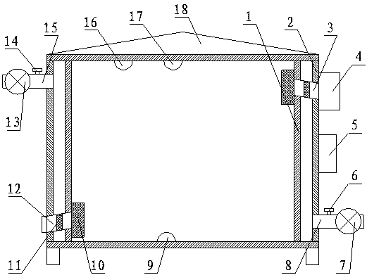
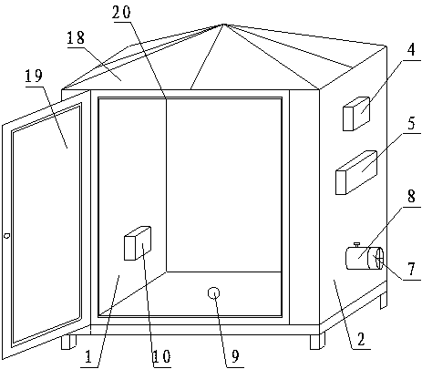
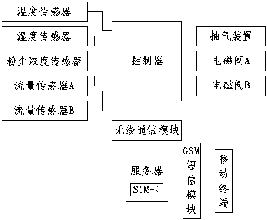
[0019] like figure 1 , figure 2 and image 3 As shown, a low-voltage distribution box for rural areas, which includes a cabinet A1, a cabinet B2 is arranged on the outside of the cabinet A1, and the cabinet A1 and the cabinet B2 are fixedly combined to form a "concave" section A font-shaped box structure, a cabinet door 19 is hinged on the opening surface of the cabinet A1, a liquid inlet pipe 15 is arranged on the left side of the cabinet B2 near the top surface, and the liquid inlet The pipe 15 is provided with a flow sensor A14 and a solenoid valve A13, and a discharge pipe 8 is provided on the right side of the cabinet B2 close to the bottom surface, and the discharge pipe 8 is provided with a flow sensor B6 and an electromagnetic valve. The valve B7, the flow sensor A14, the flow sensor B6, the solenoid valve A13 and the solenoid valve B7 are connected to the controller 5, the controller 5 is connected to a wireless communication unit, and the wireless communication un...
Embodiment 2
[0022] like figure 1 , figure 2 and image 3 As shown, a low-voltage distribution box for rural areas, which includes a cabinet A1, a cabinet B2 is arranged on the outside of the cabinet A1, and the cabinet A1 and the cabinet B2 are fixedly combined to form a "concave" section A font-shaped box structure, a cabinet door 19 is hinged on the opening surface of the cabinet A1, a liquid inlet pipe 15 is arranged on the left side of the cabinet B2 near the top surface, and the liquid inlet The pipe 15 is provided with a flow sensor A14 and a solenoid valve A13, and a discharge pipe 8 is provided on the right side of the cabinet B2 close to the bottom surface, and the discharge pipe 8 is provided with a flow sensor B6 and an electromagnetic valve. The valve B7, the flow sensor A14, the flow sensor B6, the solenoid valve A13 and the solenoid valve B7 are connected to the controller 5, the controller 5 is connected to a wireless communication unit, and the wireless communication un...
PUM
 Abstract
Description
Claims
Application Information
 - R&D
- Intellectual Property
- Life Sciences
- Materials
- Tech Scout
- Unparalleled Data Quality
- Higher Quality Content
- 60% Fewer Hallucinations
Browse by: Latest US Patents, China's latest patents, Technical Efficacy Thesaurus, Application Domain, Technology Topic, Popular Technical Reports.
© 2025 PatSnap. All rights reserved.Legal|Privacy policy|Modern Slavery Act Transparency Statement|Sitemap|About US| Contact US: help@patsnap.com


