Exhaust system and power system

A technology of exhaust system and exhaust manifold, applied in the direction of exhaust devices, engine components, machines/engines, etc., can solve the problems of exhaust system performance degradation, exhaust failure, etc., and achieve the effect of active energy regeneration

Inactive Publication Date: 2018-12-18
UNITED AUTOMOTIVE ELECTRONICS SYST
View PDF9 Cites 4 Cited by
  • Summary
  • Abstract
  • Description
  • Claims
  • Application Information

AI Technical Summary

Problems solved by technology

[0004] The purpose of the present invention is to provide an exhaust system and a power system to solve the problems of existing exhaust systems, such as performance degradation or exhaust failure, etc.

Method used


Image

  • Exhaust system and power system
  • Exhaust system and power system
  • Exhaust system and power system

Examples


Embodiment Construction

[0026] The specific implementation manner of the present invention will be described in more detail below with reference to schematic diagrams. Advantages and features of the present invention will be apparent from the following description and claims. It should be noted that all the drawings are in a very simplified form and use imprecise scales, and are only used to facilitate and clearly assist the purpose of illustrating the embodiments of the present invention.

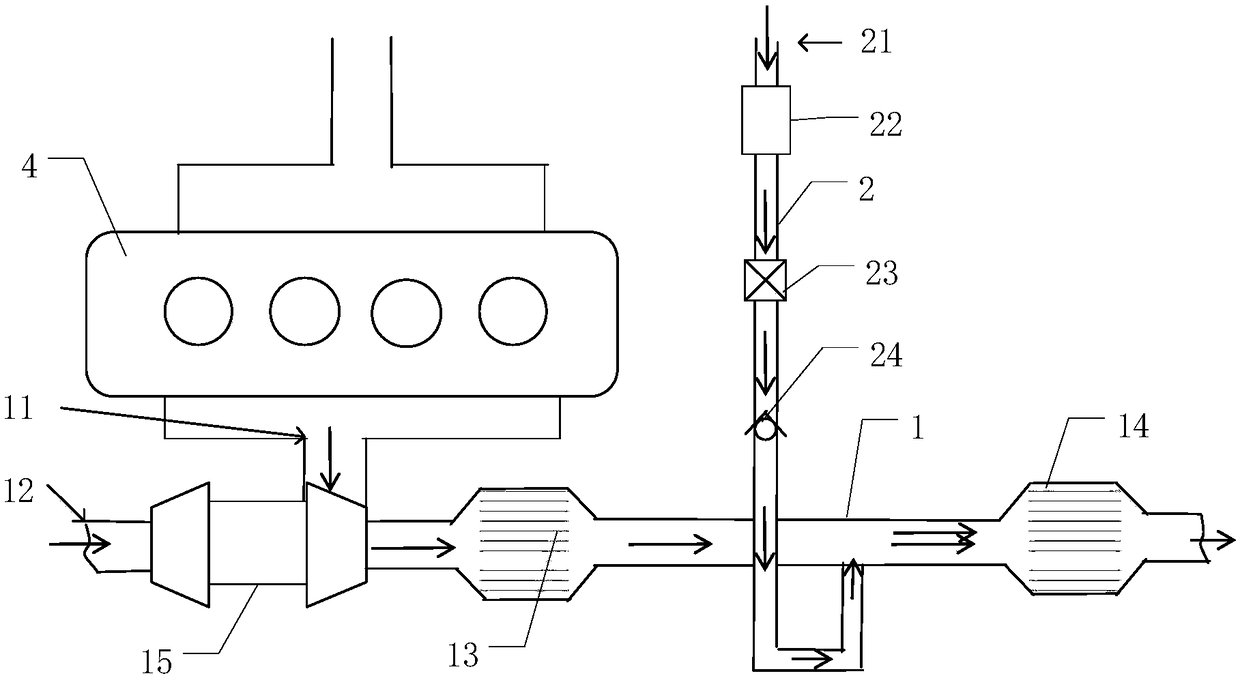
[0027] refer to figure 1 , which is a schematic diagram of an exhaust system provided in this embodiment, such as figure 1 As shown, a first pipeline 1 and a second pipeline 2 are included, and the first pipeline 1 and the second pipeline 2 all have opposite first ends and second ends; the first end of the first pipeline 1 is provided with There is a first air inlet 11, and the first air inlet 11 is used to introduce exhaust gas; the first pipeline 1 is provided with a catalytic unit 13 and a particle trapping ...


PUM


Abstract

The invention provides an exhaust system and a power system. The exhaust system comprises a first pipeline and a second pipeline. An air inlet of the first pipeline is used for leading in waste gas. One end of the second pipeline communicates with the first pipeline, and the other end of the second pipeline is used for leading in air. When waste gas flows through a catalytic unit, the waste gas iscatalyzed by the catalytic unit to generate a redox reaction, and the rest of gas flows to a particle collecting unit continuously. The particle collecting unit collects particles in the rest of gas,and an oxidation reaction is conducted on the particles and the air led in the second pipeline. Due to the fact that a large amount of heat is released through the oxidation reaction, the temperaturein the particle collecting unit is increased, the oxidation reaction can be conducted on the particles and the air continuously after the temperature in the particle collecting unit is increased, initiative regeneration of energy is achieved, and in addition, the phenomenon that the particles are accumulated in the particle collecting unit for a long term, and consequently the pipelines are blocked is avoided.

Description

technical field [0001] The invention relates to the field of automobile manufacturing equipment, in particular to an exhaust system and a power system. Background technique [0002] Automobile exhaust system refers to the system that collects and discharges exhaust gas, mainly to discharge the exhaust gas emitted by the engine, and at the same time reduce the pollution of the exhaust gas and reduce the noise. [0003] Existing automotive exhaust systems usually include an exhaust system, a catalytic converter, and a particulate filter. Due to factors such as the layout of the vehicle chassis, the exhaust system is relatively long, and the distance between the exhaust manifold of the automotive engine and the particulate filter Longer, in the environment of low speed, small load and low temperature of the car, the internal temperature of the particle filter will be low, for example, it cannot exceed 450°C, and regeneration cannot be achieved, so long-term accumulated particle...

Claims


Application Information

Patent Timeline
Patent Type & Authority Applications(China)
IPC IPC(8): F01N13/00F01N3/021F01N3/10F01N3/029F01N3/32
CPCF01N3/021F01N3/0293F01N3/101F01N3/32F01N13/009
Inventor 庄兵翁乙文
Owner UNITED AUTOMOTIVE ELECTRONICS SYST
Why Eureka
Try Eureka