Oil circulation cooling system

A technology of cooling system and oil circulation, applied in engine components, engine lubrication, lubricating parts, etc., can solve the problem of the increase of lubricating oil temperature in the oil pool of the atomizer, the increase of lubricating oil temperature, and the cooling of the bearing by the lubricating oil. Problems such as the disappearance of the effect

Pending Publication Date: 2018-12-18
无锡天阳干燥设备有限公司
View PDF0 Cites 1 Cited by
  • Summary
  • Abstract
  • Description
  • Claims
  • Application Information

AI Technical Summary

Problems solved by technology

[0003] In spray drying equipment, after the large atomizer is turned on, lubricating oil is often used to lubricate and cool the bearings in the atomizer during operation, but long-term operation will easily cause lubrication in the oil pool stored in the atomizer The ...

Method used


Image

  • Oil circulation cooling system

Examples


Embodiment Construction

[0016] The specific implementation of this embodiment will be described below in conjunction with the accompanying drawings.

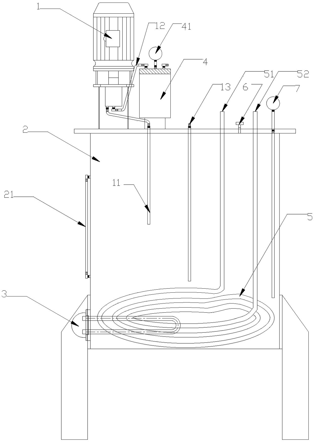
[0017] figure 1 It is a schematic diagram of the present invention. like figure 1 As shown, an oil circulation cooling system includes an oil pump 1, an oil suction pipe 11-12, an oil suction pipe 13, an oil tank 2, a heater 3, an oil tank 4, an oil tank pressure gauge 41, a cooling water pipe 5, an air vent 6 and an oil tank Thermometer7. The oil pump 1 is installed on the oil tank 2 . The side wall of the oil tank 2 is equipped with an oil tank level gauge 21. The fuel tank level gauge 21 is transparent, and the liquid level of the fuel tank 2 can be seen at the transparent part. The top of the fuel tank 2 offers air vents 6 . One end of oil extraction pipe 13 stretches in the fuel tank 2, and the other end of oil extraction pipe 13 stretches in the oil pump of the atomizer not shown among the figure. The atomizer is the prior art, not the str...


PUM


Abstract

The invention relates to an oil circulation cooling system. The oil circulation cooling system comprises an oil pump, oil sucking pipes, an oil drawing pipe, an oil box, a heater, an oil tank, a cooling water pipe, a ventilation hole, an oil box liquidometer, an oil box thermometer and an oil tank piezometer. The oil pump is mounted at the oil box. The oil drawing pipe extends into the oil box. The oil box liquidometer is mounted on the lateral wall of the oil box. One end of a first oil sucking pipe extends into an oil inlet of the oil pump. The other end of the first oil sucking pipe extendsinto the oil box. One end of a second oil sucking pipe extends into an oil outlet of the oil pump. The other end of the second oil sucking pipe extends into an oil inlet of the oil tank. A pipe bodyof the cooling water pipe is mounted in the oil box. A water inlet and a water outlet of the cooling water pipe extend out of the oil box. A heating pipe of the heater is mounted in the oil box. A temperature probe of the oil box thermometer is inserted in the oil box. A pressure probe of the oil tank piezometer is inserted in the oil tank. The oil circulation cooling system solves the problem that temperature of lubricating oil in an oil pool of a large atomizer increases after a long period of operation.

Description

technical field [0001] The invention relates to the field of cooling systems, in particular to an oil circulation cooling system. Background technique [0002] The process of using the spray drying equipment is as follows: connect the main power → turn on the centrifugal fan → preheat the drying tower → turn on the spray circulation pump, check whether the water in the water tank is sufficient and whether the concentration exceeds the standard → when the inlet air temperature reaches about 280°C, turn on Atomizer → turn on the inverter, wait for the inverter to run to the set frequency → turn on the feed pump to work at the proper flow → keep the exhaust temperature constant, adjust the feeding amount → turn on the discharger to discharge. [0003] In spray drying equipment, after the large atomizer is turned on, lubricating oil is often used to lubricate and cool the bearings in the atomizer during operation, but long-term operation will easily cause lubrication in the oil ...

Claims


Application Information

Patent Timeline
IPC IPC(8): F16N39/02
CPCF16N39/02
Inventor 邓勇王俐玲唐振秋
Owner 无锡天阳干燥设备有限公司
Why Eureka
Try Eureka