Grating protection slope surface stress and strain monitoring device and method

A surface stress and monitoring device technology, which is applied in the direction of measuring devices, optical devices, instruments, etc., can solve problems that have not been solved well, and achieve the effect of difficult monitoring, high sensitivity, and favorable re-construction

Pending Publication Date: 2018-12-18
GUANGXI UNIV +1
View PDF7 Cites 7 Cited by
  • Summary
  • Abstract
  • Description
  • Claims
  • Application Information

AI Technical Summary

Problems solved by technology

[0008] In the practical engineering application of slope monitoring system technology, there is still no good solution

Method used


Image

  • Grating protection slope surface stress and strain monitoring device and method
  • Grating protection slope surface stress and strain monitoring device and method
  • Grating protection slope surface stress and strain monitoring device and method

Examples


Embodiment 1

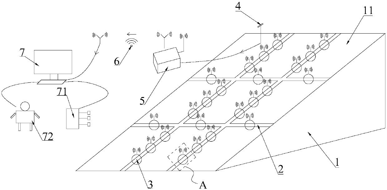
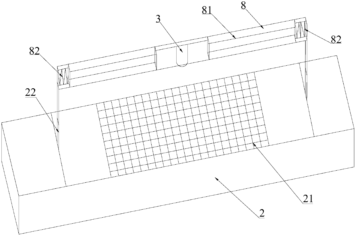
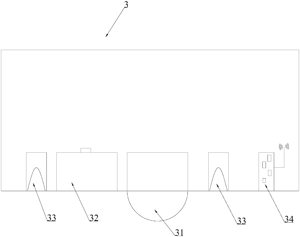
[0053] Such as Figure 1-Figure 3 As shown, a monitoring device for grid protection slope surface stress and strain includes grid lines 21, CCD monitoring box 3, power supply device 4, signal conditioning and transfer device 5, wireless transmission device 6 and data processing and display device 7 .

[0054] The CCD monitoring box 3 obtains the real-time image signal of the grid line 21, and sends it to the signal conditioning and transfer device 5, and the signal conditioning and transfer device 5 performs denoising, amplification, and signal standardization processing on the image signal Afterwards, it is sent to the data processing and display device 7 through the wireless transmission device 6 for storage, and at the same time, the data processing and display device 7 compares the image signals of the grid lines 21 at different times to obtain the deformation amount of the grid 2 and assess slope stability.

[0055] The grid lines 21 are pre-drawn on the surface of the ...

Embodiment 2

[0061] A method for monitoring stress and strain on the surface of a grid protection slope, the monitoring method is as follows:

[0062] Step 1: preset grid lines 21 on the surface of the grid 2 on the slope 11;

[0063] Step 2: the CCD monitoring box 3 is installed on the grid 2, and is positioned directly above the grid line 21;

[0064] Step 3: The CCD monitoring box 3 obtains the real-time image signal of the grid line 21;

[0065] Step 4: The CCD monitoring box 3 sends the image signal collected to the signal conditioning and transfer device 5;

[0066] Step 5: The signal conditioning and transfer device 5 performs denoising, amplification, and signal standardization processing on the image signal. Specifically, a narrowband filter is used to filter the received image signal, and an adaptive algorithm is used to perform inter-symbol interference Inhibition, to achieve the optimization of spread spectrum communication;

[0067] Step 6: The signal conditioning and trans...


PUM


Abstract

The invention discloses a grating protection slope surface stress and strain monitoring device and method. The monitoring device comprises grid lines, a CCD monitoring box, a power supply device, a signal conditioning and transferring device, a wireless transmission device and a data processing and displaying device; the grid lines are pre-arranged on the surface of a grating; the CCD monitoring box is fixed to the grating, and is located over the grid lines; the power supply device provides a power supply for the signal conditioning and transferring device; the CCD monitoring box acquires real-time image signals of the grid lines and sends the real-time image signals to the signal conditioning and transferring device; the signal conditioning and transferring device performs noise elimination, amplification and signal standardization processing on the image signals; the image signals are sent to the data processing and displaying device for performing storage through the wireless transmission device; and meanwhile, the data processing and displaying device compares the image signals of the grid lines at different moments to obtain the deformation of the grating and evaluating the slope stability.

Description

technical field [0001] The invention relates to the technical field of slope engineering deformation monitoring, in particular to a monitoring device and method for monitoring stress and strain on the surface of a grid protection slope. Background technique [0002] As a geological disaster, slope instability is common in various engineering constructions. Slope instability disasters seriously affect the design, construction and operation of engineering facilities, threatening the safety of people's lives and property. Slope engineering stability is one of the important directions of geotechnical engineering research, and slope instability will affect the feasibility, safety and economy of engineering construction. In order to ensure the safety of project construction and operation, long-term, effective and accurate monitoring of slopes, predicting the state of slopes in advance, providing a basis for decision-making and evaluation, and reducing the hazards of slope instabil...

Claims


Application Information

Patent Timeline
IPC IPC(8): G01B11/16
CPCG01B11/16Y02A10/23
Inventor 巫志文董宏源汤冬云梅国雄赵艳林
Owner GUANGXI UNIV
Why Eureka
Try Eureka