Cube prism optical calibration device for aiming and monitoring optical axis of telescope

A cubic prism and telescope technology, applied in measuring devices, testing optical performance, optical instrument testing, etc., can solve the problems of theodolite fixed error, cumbersome process, and low repeatability, and achieve a simple and compact structure, easy to test, and easy to build Effect

Pending Publication Date: 2018-12-18
SHANGHAI INST OF TECHNICAL PHYSICS - CHINESE ACAD OF SCI
View PDF0 Cites 8 Cited by
  • Summary
  • Abstract
  • Description
  • Claims
  • Application Information

AI Technical Summary

Problems solved by technology

Establishing a benchmark in this way will introduce various errors, such as the fixed error of the theodolite, the zero position error of adjusting the level of theodolite, the rotation error introduced

Method used


Image

  • Cube prism optical calibration device for aiming and monitoring optical axis of telescope
  • Cube prism optical calibration device for aiming and monitoring optical axis of telescope
  • Cube prism optical calibration device for aiming and monitoring optical axis of telescope

Examples


Embodiment Construction

[0019] The implementation examples of the patented method will be described in detail below in conjunction with the accompanying drawings.

[0020] The main components used in this patent are explained:

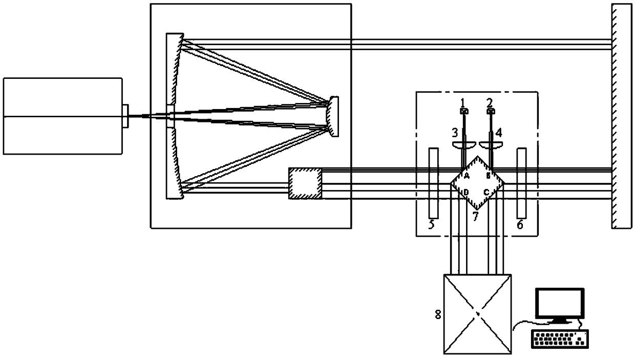
[0021] No. 1 laser diode 1 and No. 2 laser diode 2: use ThorLab's model HL6312G laser diode with a wavelength of 635nm, a power of 5mw, a diameter of 5.6mm, and a type A pin.

[0022] No. 1 collimating lens 3 and No. 2 collimating lens 4: adopt the collimating lens of ThorLab company model A230, with an aperture of 6.34 mm, a focal length of 4.51 mm, a central wavelength of 780 nm, and a material of S-NPH1.

[0023] No. 1 parallel plate 5, No. 2 parallel plate 6: customized processing, diameter 50mm, parallelism of both sides better than 3 seconds, transmitted wavefront RMS better than 1 / 15 wavelength, material K9.

[0024] Cube prism 7: customized processing, side length 35mm, 90-degree angular difference and pyramidal difference are better than 3 seconds, each surface type...


PUM


Abstract

The invention discloses a cube prism optical calibration device for aiming and monitoring an optical axis of a telescope. The cube prism optical calibration device turns two laser beams into an angleof 180 degrees using a cubic prism method, which realizes the initial adjustment of the optical axis of a telescope optical system parallel to a reference standard plane mirror normal. The parallel relationship between two parallel plates is adopted to solve the high-precision precision adjustment of the optical axis of the telescope parallel to the reference plane mirror normal. According to thecube prism optical calibration device for aiming and monitoring an optical axis of a telescope, the problem of image quality change caused by the drift of the optical axis during the telescope adjustment process is solved, and real-time high-precision monitoring of the state of the tested system is realized. The optical path structure is simple, and the combination of coarse adjustment and fine adjustment greatly improves the efficiency of optical calibration. The optical calibration device of the invention is not only suitable for registration and real-time monitoring of the optical axis of the telescope optical system and the standard plane mirror normal, but also suitable for calibrating the angle between two opposite mirror surfaces, the angle between two optical plates, and other optical calibration fields.

Description

technical field [0001] The invention relates to the alignment of the optical axis of the telescope optical system and the registration of the transceiver coaxial in the performance test of the whole system, and is especially suitable for the registration and real-time monitoring of the optical axis of the telescope optical system and the normal line of the standard plane mirror during the assembly and adjustment of the reflective telescope. It is also suitable for calibrating the angle between two opposing mirrors, the angle between two optical flat plates and other optical calibration fields. Background technique [0002] The optical system loads of space reflective space cameras such as laser altimeter and laser radar have higher and higher requirements for optical axis pointing, which will inevitably lead to higher and higher requirements for optical axis registration in the optical calibration process of the optical system. During the self-collimation optical calibration...

Claims


Application Information

Patent Timeline
IPC IPC(8): G01M11/02
CPCG01M11/00
Inventor 刘强王欣窦永昊黄庚华何志平舒嵘
Owner SHANGHAI INST OF TECHNICAL PHYSICS - CHINESE ACAD OF SCI
Why Eureka
Try Eureka