Nano-amplified self-reference probe for in-situ imaging of microRNA in living cells and preparation method thereof

A living cell and large self-reference technology, applied in the field of nano-amplified self-reference probes and its preparation, can solve problems such as difficult to maintain data stability and reliability, poor stability of nucleic acid probes, difficult miRNA signals, etc., to achieve Effects of fluorescence imaging and relative quantitative detection, improvement of detection specificity, and improvement of sensitivity

Active Publication Date: 2018-12-18
NANJING UNIV
View PDF3 Cites 4 Cited by
  • Summary
  • Abstract
  • Description
  • Claims
  • Application Information

AI Technical Summary

Problems solved by technology

However, they cannot fully solve the following three problems in the imaging detection of intracellular miRNA: (1) It is difficult to effectively amplify the signal of miRNA with low abundance in the cell; (3) Due to the lack of internal reference, the signal intensity obtained in the experiment is affected by the fluctuation of instrument parameters, and it is difficult to maintain the stability and reliability of the data

Method used


Image

  • Nano-amplified self-reference probe for in-situ imaging of microRNA in living cells and preparation method thereof
  • Nano-amplified self-reference probe for in-situ imaging of microRNA in living cells and preparation method thereof

Examples


Embodiment 1

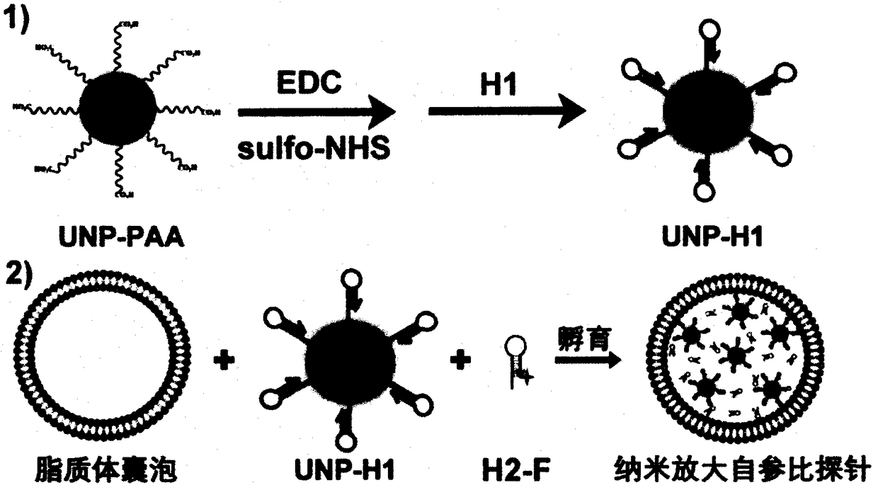
[0020] Example 1: Combining figure 1 , to prepare probes.

[0021] The probe preparation process is divided into two steps: 1) preparation of UNP-H1, and 2) preparation of probe by wrapping UNP-H1 and H2-F with lipo-3000.

[0022] 1) Preparation of UNP-H1: Taking the detection of miR21 in living cells as an example, the nucleotide sequence of H1 is 5’NH 2 - TCAACATCAGTCTGATAAGCTACCATGTGTAGATAGCTTTATCAGACT; H2 is TAAGCTATCTACACATGGTAGCTTATCAGACTCCATGTGTAGA-F-3'. UNP to NaYF 4 : Er / Gd / Yb@NaGdF 4 For example, EEB1 is at 530-560nm, and EEB2 is at 640-670nm. F Take AF555 as an example, its absorption peak overlaps with EEB1. 15.3 mg EDC (final concentration: 0.4 μM) and 4.34 mg sulfo-NHS (final concentration: 0.1 μM) were quickly added to 200 μL of PBS solution containing 1 mg / mL PAA-UNP, and shaken at room temperature for 4 h. Carboxyl-activated PAA-UNP was prepared by removing excess EDC and sulfo-NHS by centrifugation and redispersing to 200 μL. H1 was then added to the a...

Embodiment 2

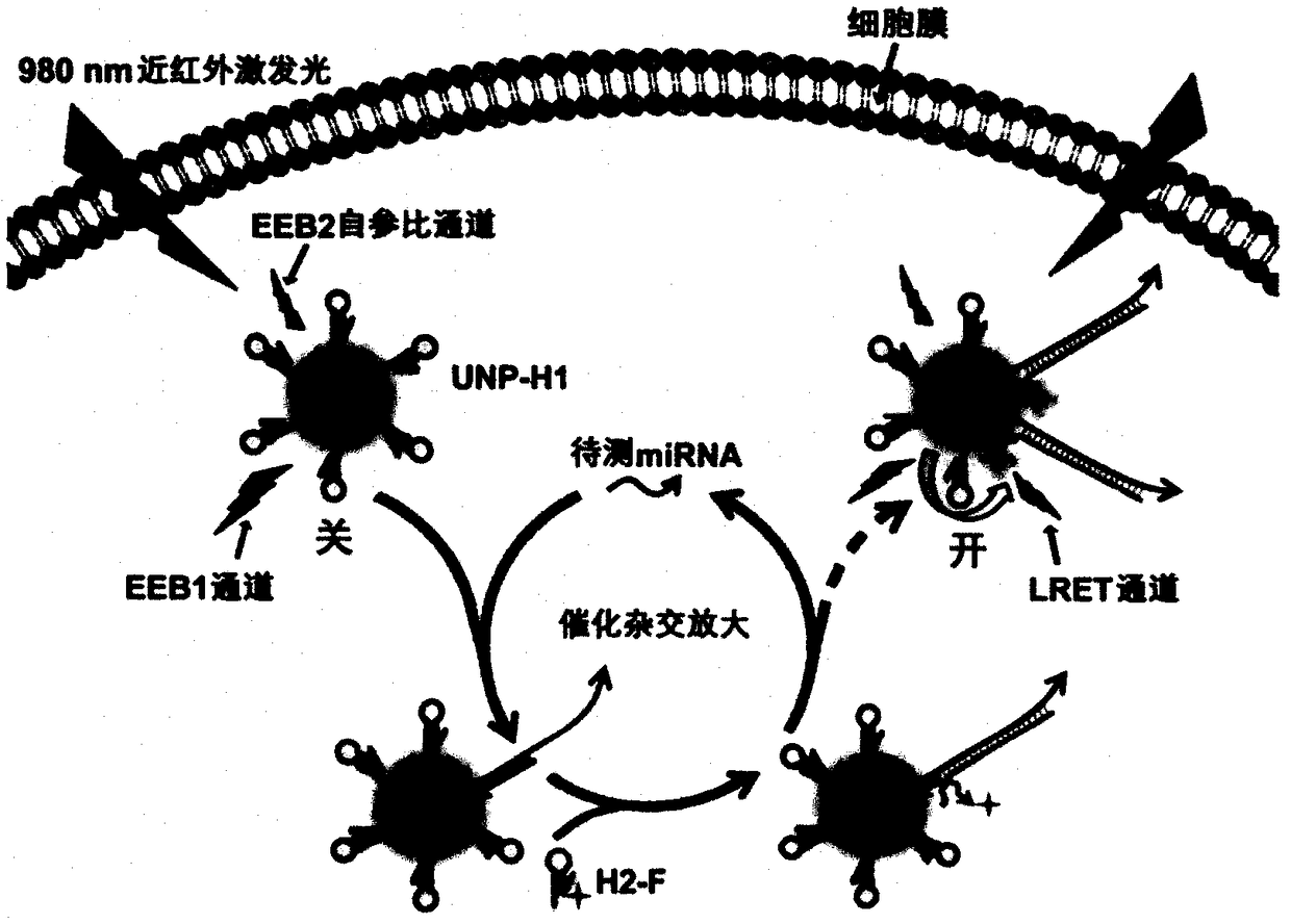
[0024] Example 2: Combining figure 2 , using the nano-amplified self-reference probe for in situ imaging and relative quantification of miRNAs in living cells.

[0025] Taking the detection of miR21 in MDA-MB-231 breast cancer cells as an example, the concentration of 0.5mL was 1×10 6 mL -1 The cell suspension was seeded in a 20-mm four-well confocal culture dish and cultured for 24 hours. Then, the nano-amplified self-reference probe prepared above was added to the culture dish (150 μL / well), and after co-incubating with the cells for 6 h, under the excitation of 980 nm near-infrared light, the LRET channel was imaged using a laser confocal fluorescence microscope. The fluorescence distribution map of the miRNA to be tested in cancer cells can be obtained. Read the signal intensity of LRET and EEB2 channels in single cell area respectively by confocal software, and calculate its ratio (I LRET / I EEB2 ), this ratio represents the expression level of the miRNA to be teste...


PUM


Abstract

The invention relates to a nano-amplified self-reference probe for in-situ imaging of microRNA (miRNA) in living cells and a preparation method thereof. The probe is formed by encapsulating a nucleicacid hairpin modified upper conversion nanoparticle (UNP-H1) and a fluorescent molecule modified hairpin molecule (H2-F) through a liposome. When the probe enters a cell, UNP-H1 and H2-F are released,and only when H1 is hybridized to the miRNA, H2 can replace the miRNA to hybridize with UNP-H1, and the released miRNA starts the next cycle to amplify a signal. Under excitation of near-infrared light, luminescence resonance energy transfer (LRET) occurs between the emission band 1 (EEB1) and F of the UNP. The luminescence intensity ratio of the LRET and EEB2 channels (ILRET/IEEB2) can be used for relative quantification of intracellular miRNA taking emission band 2 (EEB2) channel of the UNP as a self-reference.

Description

1. Technical field [0001] The invention relates to a nano-amplified self-reference probe for in-situ imaging of intracellular microRNA and a preparation method thereof. 2. Background technology [0002] MicroRNA (miRNA) is an important tumor marker, and its distribution and expression level in cells are closely related to the occurrence and development of cancer. Therefore, in situ imaging and detection of intracellular miRNA is of great significance for early diagnosis and prognosis monitoring of tumors. Probes commonly used for intracellular miRNA imaging are mainly divided into two categories: molecular beacons (MBs) and nucleic acid functionalized nanoprobes. However, they cannot fully solve the following three problems in the imaging detection of intracellular miRNA: (1) It is difficult to effectively amplify the signal of miRNA with low abundance in the cell; (3) Due to the lack of internal reference, the signal intensity obtained in the experiment is affected by the...

Claims


Application Information

Patent Timeline
Patent Type & Authority Applications(China)
IPC IPC(8): G01N21/64
CPCG01N21/6486
Inventor 丁霖鞠熀先霍敏
Owner NANJING UNIV
Why Eureka
Try Eureka