
Power detection alarm device with automatic take-up function

A technology of electric power detection and alarm device, which is applied in the direction of measuring device, measuring electricity, measuring electric variables, etc., can solve the problems of affecting the operating efficiency of operators, cumbersome operation, and small application range, so as to increase the application range of measurement and simple operation Convenience, the effect of convenient line arrangement

Inactive Publication Date: 2018-12-18
姜平
View PDF9 Cites 1 Cited by
  • Summary
  • Abstract
  • Description
  • Claims
  • Application Information

AI Technical Summary

Problems solved by technology

It converts the primary energy in nature into electricity through mechanical energy devices, and then supplies the electricity to various users through power transmission, transformation and distribution. For the safety of electricity consumption by each household, it is necessary to regularly conduct power inspections on relevant lines or power supply components. The existing power detection single wiring process has few operation methods and a small scope of application. The detection wiring is prone to entanglement or the wiring is too short. process, affecting the operating efficiency of operators, and the circuit detection device is placed for a long time, and the interior is damp, causing some electronic components to rust and affecting the service life

Method used


Image

  • Power detection alarm device with automatic take-up function
  • Power detection alarm device with automatic take-up function
  • Power detection alarm device with automatic take-up function

Examples


Embodiment Construction

[0021] The technical solutions in the embodiments of the present invention will be clearly and completely described below in conjunction with the accompanying drawings in the embodiments of the present invention. Obviously, the described embodiments are only a part of the embodiments of the present invention, rather than all the embodiments. Based on the embodiments of the present invention, all other embodiments obtained by those of ordinary skill in the art without creative work shall fall within the protection scope of the present invention.

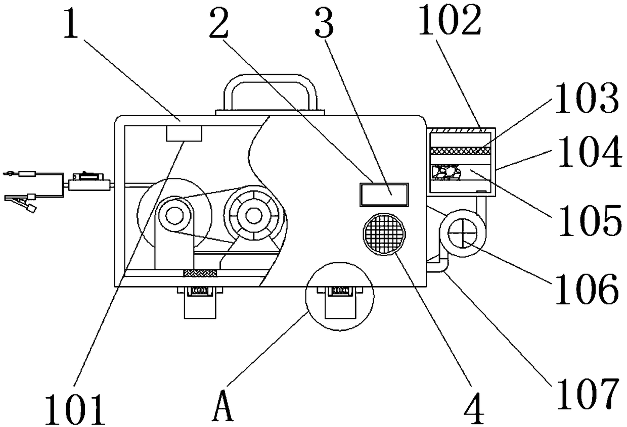
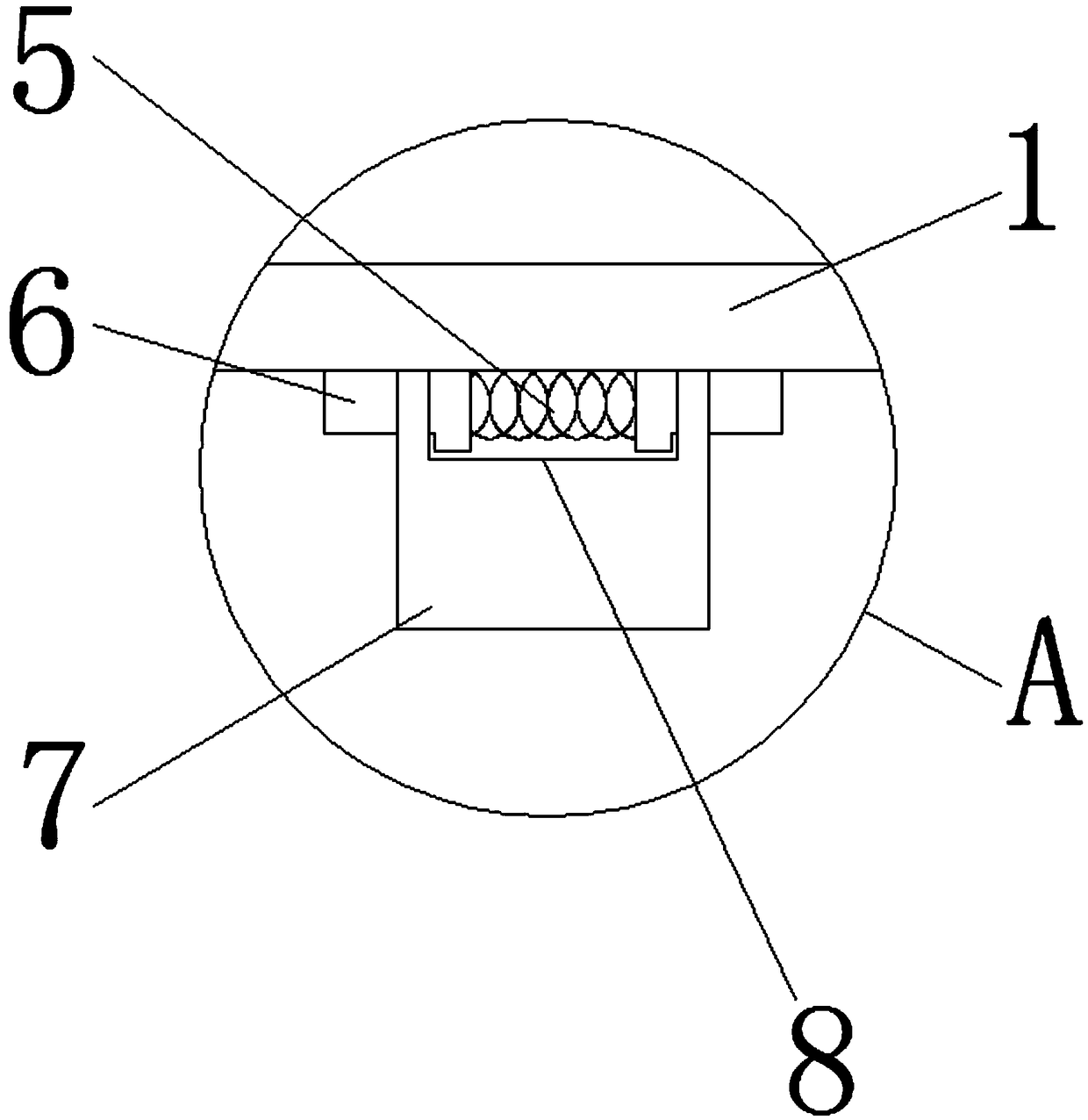
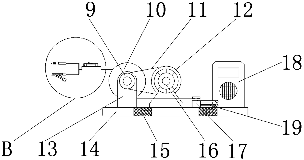
[0022] See Figure 1~5 In the embodiment of the present invention, an alarm device for power detection with automatic take-up function includes a protective box 1, a rectangular groove 2, a glass baffle 3, a circular groove 4, an installation spring 5, a T-shaped lever 6, a card Block 7, cavity 8, driven wheel 9, storage roller 10, belt 11, driving wheel 12, vertical plate 13, bottom plate 14, mounting slot 15, motor 16, wiring block 17,...


PUM


Abstract

The invention discloses a power detection alarm device with an automatic take-up function, which comprises a protection box and a rectangular groove. The operating process of the power detection alarmdevice is that: an electric motor is directly started up; by rotation of a driving wheel, a belt and a driven wheel, two storage rollers are driven to continuously rotate; two groups of third wires are continuously lengthened; when the lengthened length meets the requirement, the electric motor is shut down; the third wires are pulled out of the inside of a passage; a wire or an electronic component which needs to be measured is fixed by a connection plug or an electrical connection wire clamp; in the electrical connection process, an illumination lamp is turned on; after electrical connection is completed, a multimeter can automatically identify electric power safety so as to facilitate detection of people; and for the protection box, a mounting spring can be squeezed by squeezing two T-shaped clamping rods symmetrically arranged so as to facilitate removing the integral protection box and facilitate internal installation of the integral detection device. According to the invention,the protection box reinforces collision resistance and waterproofness of the integral detection device; and the power detection alarm device is applicable to detection on various lines and electric equipment, is simple and convenient to operate and is convenient for an operator to use, so that working efficiency is improved.

Description

Technical field [0001] The invention relates to an alarm device, in particular to an alarm device for power detection with an automatic wire-taking function. Background technique [0002] Electricity is an energy source that uses electric energy as power. Invented in the 1870s, the invention and application of electric power set off the second wave of industrialization. It has become one of the three technological revolutions in the world since the 18th century of human history. Since then, technology has changed people's lives. The large-scale power system that emerged in the 20th century is one of the most important achievements in the history of human engineering science. It is a power production and consumption system composed of power generation, transmission, transformation, distribution, and power consumption. It converts the primary energy in nature into electricity through mechanical energy devices, and then supplies electricity to users through power transmission, tra...

Claims


Application Information

Patent Timeline
Patent Type & Authority Applications(China)
IPC IPC(8): G01R31/00
CPCG01R31/00
Inventor 姜平宋建军刘可夫常亮卫东徐振国龚庆东魏强宋明利任传柱叶剑李金艳
Owner 姜平
Learn More