A composite ventilation cooling system of a main transformer room

A main transformer room and composite ventilation technology, which is applied in the field of ventilation systems, can solve problems such as short circuit of air flow, insufficient exhaust power, and difficult air flow, so as to increase the exhaust rate and flow rate, reduce the number of units used and the frequency of opening , to avoid the effect of air short circuit phenomenon

Inactive Publication Date: 2018-12-18
SOUTHEAST UNIV
View PDF5 Cites 14 Cited by
  • Summary
  • Abstract
  • Description
  • Claims
  • Application Information

AI Technical Summary

Problems solved by technology

Especially in the area between the main transformer and the radiator, due to the narrow space and the dense distribution of circulating oil pipes and cooling fins, the air flow is relatively difficult, and the oil flow temperature at the transformer outlet is high, which is prone to local heat accumulation problems
[0005] In addition, due to the high height of the main transformer room, the problem of insufficient exhaust power is likely to occur in the upper and middle spaces of the room, and the air flow in some areas is slow and prone to disorderly flow, and the hot air carrying heat gathers in the room and cannot be discharged in time
However, in the existing part of the ventilation system, the natural air intake louvers and the natural exhaust louvers are designed on the same side wall, which is prone to adverse results of airflow short circuit

Method used


Image

  • A composite ventilation cooling system of a main transformer room
  • A composite ventilation cooling system of a main transformer room
  • A composite ventilation cooling system of a main transformer room

Examples


Embodiment Construction

[0030] The technical solution of the present invention will be further described below in conjunction with the accompanying drawings.

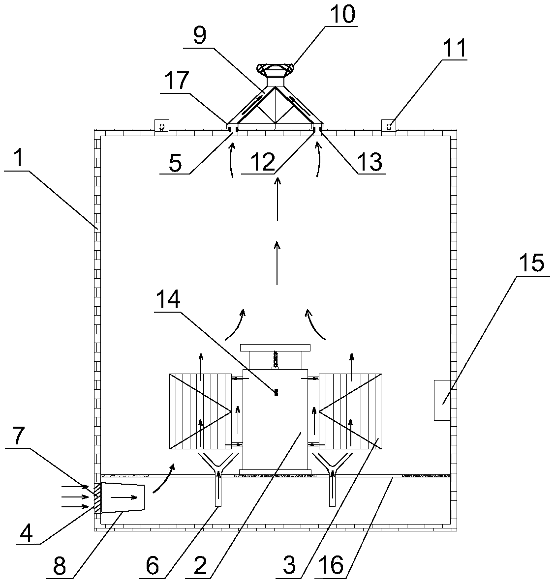
[0031] Such as figure 1 As shown, a composite ventilation and cooling system for a main transformer room of the present invention includes a main transformer room 1, an integrated oil-immersed transformer located in the center of the main transformer room 1, an integrated oil-immersed transformer located below the integrated oil-immersed transformer, and close to the bottom of the main transformer room 1. The air intake system, the exhaust system with the top of the main transformer room 1 and the control system for intelligent control. The integrated oil-immersed transformer of the present invention includes a transformer body 2 and radiators 3 located on both sides of the transformer body 2 , and an oil delivery pipe is connected between the radiator 3 and the transformer body 2 . The main transformer room 1 is provided with a ventilation g...


PUM


Abstract

The invention discloses a composite ventilation cooling system of a main transformer room, including the main transformer room, an integrated oil-immersed transformer located in the center of the maintransformer roomroom, an air inlet system located below the integrated oil-immersed transformer and near the bottom of the main transformer room, an exhaust system located at the top of the main transformer room and a control system for intelligent control, the integrated oil-immersed transformer comprises a transformer body and radiators located on both sides of the transformer body, an air inlet is arranged at the bottom of one side wall of the main transformer room and an air outlet is arranged at the top of the main transformer room. The invention makes full use of external environmentalconditions to strengthen a ventilation effect, According to the operation of transformer and indoor ventilation condition, the ventilation mode can be adjusted dynamically, the indoor air flow can flow from bottom to top orderly, the utilization efficiency of cooling air can be improved, the service time of a mechanical fan is reduced, and the ventilation energy consumption can be reduced while the ventilation heat exchange effect of the transformer room can be improved.

Description

technical field [0001] The invention relates to a ventilation system for a main transformer room, in particular to a composite ventilation cooling system for a main transformer room. Background technique [0002] Because urban substations are located in urban areas, the land area is limited, and the impact of noise generated by operation on the surrounding environment must be considered, so electrical equipment such as main transformers are usually arranged indoors. For substations arranged indoors, oil-immersed transformers are often used, and the heat generated by the main transformer and radiator is a potential threat to its safe operation. In order to maintain the oil temperature of the transformer within a reasonable range and ensure smooth operation during the peak period of power consumption, it is very important to solve the ventilation and heat dissipation problems of indoor equipment. Therefore, it is necessary to discharge the heat dissipation during the operatio...

Claims


Application Information

Patent Timeline
Patent Type & Authority Applications(China)
IPC IPC(8): H02B1/56H02B1/28F24S60/10
CPCH02B1/565H02B1/28
Inventor 黄亚继秦文慧曹健华陈浩夏志鹏
Owner SOUTHEAST UNIV
Why Eureka
Try Eureka