A switching power supply and a control chip thereof

A control chip and switching power supply technology, applied in the field of electronics, can solve the problems of increasing system cost and low practicability, and achieve the effect of avoiding the phenomenon of saturation

Active Publication Date: 2018-12-18
SHENZHEN WINSEMI MICROELECTRONICS
View PDF7 Cites 1 Cited by
  • Summary
  • Abstract
  • Description
  • Claims
  • Application Information

AI Technical Summary

Problems solved by technology

[0005] For the above problems, a feasible solution is to connect clamping diodes in parallel at both ends of the VCC power supply capacitor to reduce or remove the spike of the VCC voltage, thereby avoiding the phenomenon of inductor current saturation, but this requires additional system costs, practical lower sex

Method used


Image

  • A switching power supply and a control chip thereof
  • A switching power supply and a control chip thereof
  • A switching power supply and a control chip thereof

Examples


Embodiment Construction

[0034]The present invention provides a switching power supply and its control chip. In order to make the purpose, technical solution and effect of the present invention clearer and clearer, the present invention will be further described in detail below with reference to the accompanying drawings and examples. It should be understood that the specific embodiments described here are only used to explain the present invention, not to limit the present invention.

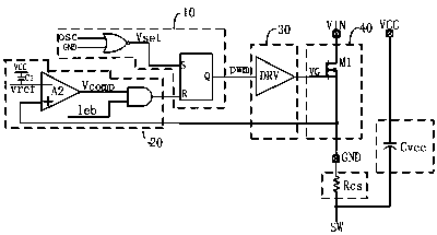
[0035] see image 3 The control chip of the switching power supply provided by the present invention includes a logic circuit 10, an OCP comparison circuit 20, a drive circuit 30, a power switch tube circuit 40, and a PWM signal pulse width sampling and comparison circuit 50; wherein, the output of the logic circuit 10 terminal is connected to the input terminal of the drive circuit 30 and the input terminal of the PWM signal pulse width sampling and comparison circuit 50, the output terminal of the drive circuit 30 is...


PUM


Abstract

The invention discloses a switching power supply and a control chip thereof. The control chip comprises a logic circuit, an OCP comparison circuit, a driving circuit, a power switch transistor circuitand a PWM signal pulse width sampling and comparison circuit. The output end of the logic circuit is connected with the input end of the driving circuit and the input end of the PWM signal pulse width sampling and comparing circuit, The output end of the driving circuit is connected with the input end of the power switch circuit, the output end of the OCP comparing circuit is connected with the input end of the logic circuit, and the output end of the PWM signal pulse width sampling and comparing circuit is connected with the input end of the OCP comparing circuit. As that pulse width sampleand comparing circuit of the PWM signal is increase, the inductor current can be turned off in time when the system is disturbed by noise and the VCC voltage waveform is sharp, and the inductor current saturation phenomenon is avoided.

Description

technical field [0001] The invention relates to the field of electronic technology, in particular to a switching power supply and a control chip thereof. Background technique [0002] A general BUCK type AC-DC switching power supply system consists of an input capacitor, a control chip, a chip power supply capacitor, an energy storage inductor, a freewheeling diode, an output feedback diode, a sampling resistor, an output capacitor and a load. figure 1 Shown is a simplified schematic of the control chip for a switching power supply. for figure 1 The power tube M1 shown is turned on by the internal clock OSC controlling the PWM signal, and the power tube is turned off by resetting the PWM signal after the sampling resistor detects that the voltage VRcs reaches the reference voltage vref, and the power tube M1 The corresponding inductor current value at shutdown is the OCP threshold, I_OCP=vref / Rcs. [0003] This kind of system architecture is called floating ground archite...

Claims


Application Information

Patent Timeline
IPC IPC(8): H02M7/217H02M1/44
CPCH02M1/44H02M7/217
Inventor 白文利宋利军
Owner SHENZHEN WINSEMI MICROELECTRONICS
Why Eureka
Try Eureka