Scanning method for restraining bending deformation of laser-welded thin plate

A technology of laser welding and bending deformation, used in laser welding equipment, welding equipment, manufacturing tools, etc., to improve welding efficiency and quality, reduce temperature gradients, and be easy to operate.

Active Publication Date: 2018-12-21
JIANGSU UNIV
View PDF16 Cites 2 Cited by
  • Summary
  • Abstract
  • Description
  • Claims
  • Application Information

AI Technical Summary

Problems solved by technology

[0004] The purpose of the present invention is to solve the problems existing in the prior art, to provide a scanning method for suppressing the bending deformation of laser welding sheet metal, and to suppress the deformation of sheet metal welding by controlling reasonable heat input, starting from changing the action time of laser and workpiece , by changing the conventional laser welding scanning method to improve the heat input of laser energy, thereby suppressing the deformation of the metal sheet welded parts, and improving the efficiency and quality of sheet welding

Method used


Image

  • Scanning method for restraining bending deformation of laser-welded thin plate

Examples


Embodiment 1

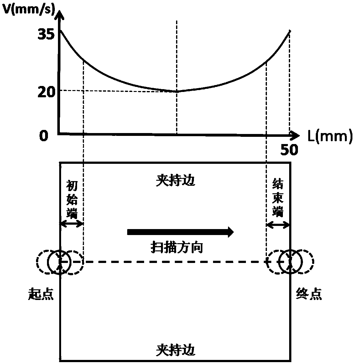
[0030] On the basis of clamping and fixing the free edges on both sides of the thin plate, by adopting the "symmetrical parabola" type variable speed scanning method, on the premise of ensuring reasonable laser heat input, to reduce the heat input caused by excessive heat input at the first and last ends of the thin plate welding The pit collapses, while reducing the undesired bending deformation during the welding process, the steps are:

[0031] Step S1: Weld a 1.5mm thick Q235 thin plate sample, pre-treat the surface of the sample by grinding, polishing, cleaning and drying, and place the pre-treated sample in a thermostat at 200°C for 1 hour for preheating ;

[0032] Step S2: Place the preheated Q235 thin plate sample with the surface to be processed facing up, fix it on the welding table with the existing special welding fixture, and restrict the movement of the workpiece by pressing the free edges on both sides. The free edge compression on both sides refers to the use ...

Embodiment 2

[0037] On the basis of clamping and fixing the free edges on both sides of the thin plate, by adopting the "symmetrical parabola" type variable speed scanning method, on the premise of ensuring reasonable laser heat input, to reduce the heat input caused by excessive heat input at the first and last ends of the thin plate welding The pit collapses, while reducing the undesired bending deformation during the welding process, the steps are:

[0038] Step S1: Weld a 0.5mm thick Q235 thin plate sample, pre-treat the surface of the sample by grinding, polishing, cleaning and drying, and place the pre-treated sample in a thermostat at 200°C for 1 hour for preheating ;

[0039] Step S2: Fix the preheated Q235 thin plate sample on the welding table with the surface to be processed facing upward, and use the free edge compression method on both sides to limit the movement of the workpiece;

[0040] Step S3: Set laser welding process parameters: laser power is 2300W, defocus amount is ...

Embodiment 3

[0044] On the basis of clamping and fixing the free edges on both sides of the thin plate, by adopting the "symmetrical parabola" type variable speed scanning method, on the premise of ensuring reasonable laser heat input, to reduce the heat input caused by excessive heat input at the first and last ends of the thin plate welding The pit collapses, while reducing the undesired bending deformation during the welding process, the steps are:

[0045] Step S1: Weld a 2mm thick Q235 thin plate sample, grind, polish, clean and dry the surface of the sample, and place the pretreated sample in a thermostat at 200°C for 1 hour for preheating;

[0046] Step S2: Fix the preheated Q235 thin plate sample on the welding table with the surface to be processed facing upward, and use the free edge compression method on both sides to limit the movement of the workpiece;

[0047] Step S3: Set the laser welding process parameters: the laser power is 2500W, the defocus is 0mm, the spot diameter is 0...


PUM

PropertyMeasurementUnit
thicknessaaaaaaaaaa
Defocus amountaaaaaaaaaa
diameteraaaaaaaaaa

Abstract

The invention provides a scanning method for restraining bending deformation of a laser-welded thin plate. The scanning method comprises the steps: step S1, before welding, preprocessing the surface of a thin plate sample to be welded, and preheating the preprocessed sample; step S2, fixing the face to be processed of the preheated thin plate sample on a welding workbench upwards; step S3, settinglaser welding process parameters; and step S4, controlling the scanning speed for laser scanning welding for the sample by adopting a symmetric parabola type variable-speed scanning method accordingto the change law of a quadratic parabola. Under the premise of ensuring reasonable laser heat input, the conventional constant scanning speed is changed to the symmetric parabola type scanning speed,so that the scanning method improves the uneven distribution of temperature and stress on a scanning line and reduces pit collapse in the initiating end and the tail end of a welding bead. Meanwhile,the scanning method can also restrain the undesired bending deformation of the thin plate during welding.

Description

technical field [0001] The invention relates to the technical field of laser welding of thin plates, in particular to a scanning method for suppressing the bending deformation of laser welded thin plates, which is suitable for high-efficiency and high-quality welding of thin plates. Background technique [0002] Sheet metal is widely used in medical equipment, microelectronics, precision instruments, automobiles, aerospace and other fields, and the connection of sheet metal is involved in the engineering manufacturing process. Sheet metal connection is usually dominated by welding, among which the laser welding method is the most representative. This welding method has the advantages of high energy density, small heat-affected zone, small welding residual stress and stress-strain, etc., and is gradually applied to sheet metal. connect. When laser welding thin plates, the welding is mainly carried out in such a way that the metal sheet remains still and the laser welding hea...

Claims


Application Information

Patent Timeline
Patent Type & Authority Applications(China)
IPC IPC(8): B23K26/082B23K26/70
CPCB23K26/082B23K26/70B23K26/702
Inventor 崔承云张文龙崔熙贵李晓东阮仲伟潘金鑫万天一孟帅
Owner JIANGSU UNIV
Why Eureka
Try Eureka