Pre-split blasting combined explosive charging method, explosive charging structure and auxiliary device

A technology of pre-splitting blasting and auxiliary devices, applied in blasting and other directions, can solve the problems of high labor intensity and low charging efficiency, and achieve the effect of reducing labor intensity, reducing manpower and material resources, and ensuring the quality of charging

Active Publication Date: 2018-12-21
CHINA GEZHOUBA GRP YIPULI CO LTD
View PDF3 Cites 7 Cited by
  • Summary
  • Abstract
  • Description
  • Claims
  • Application Information

AI Technical Summary

Problems solved by technology

[0005] The first purpose of the present invention is to provide a method for pre-splitting blasting combined charge in order to solve the problems of low charge efficiency and high labor intensity in the prior art. The method is a modular charge method, which can effectively reduce labor intensity, Save manpower and improve the efficiency of charging

Method used


Image

  • Pre-split blasting combined explosive charging method, explosive charging structure and auxiliary device
  • Pre-split blasting combined explosive charging method, explosive charging structure and auxiliary device
  • Pre-split blasting combined explosive charging method, explosive charging structure and auxiliary device

Examples


Embodiment 1

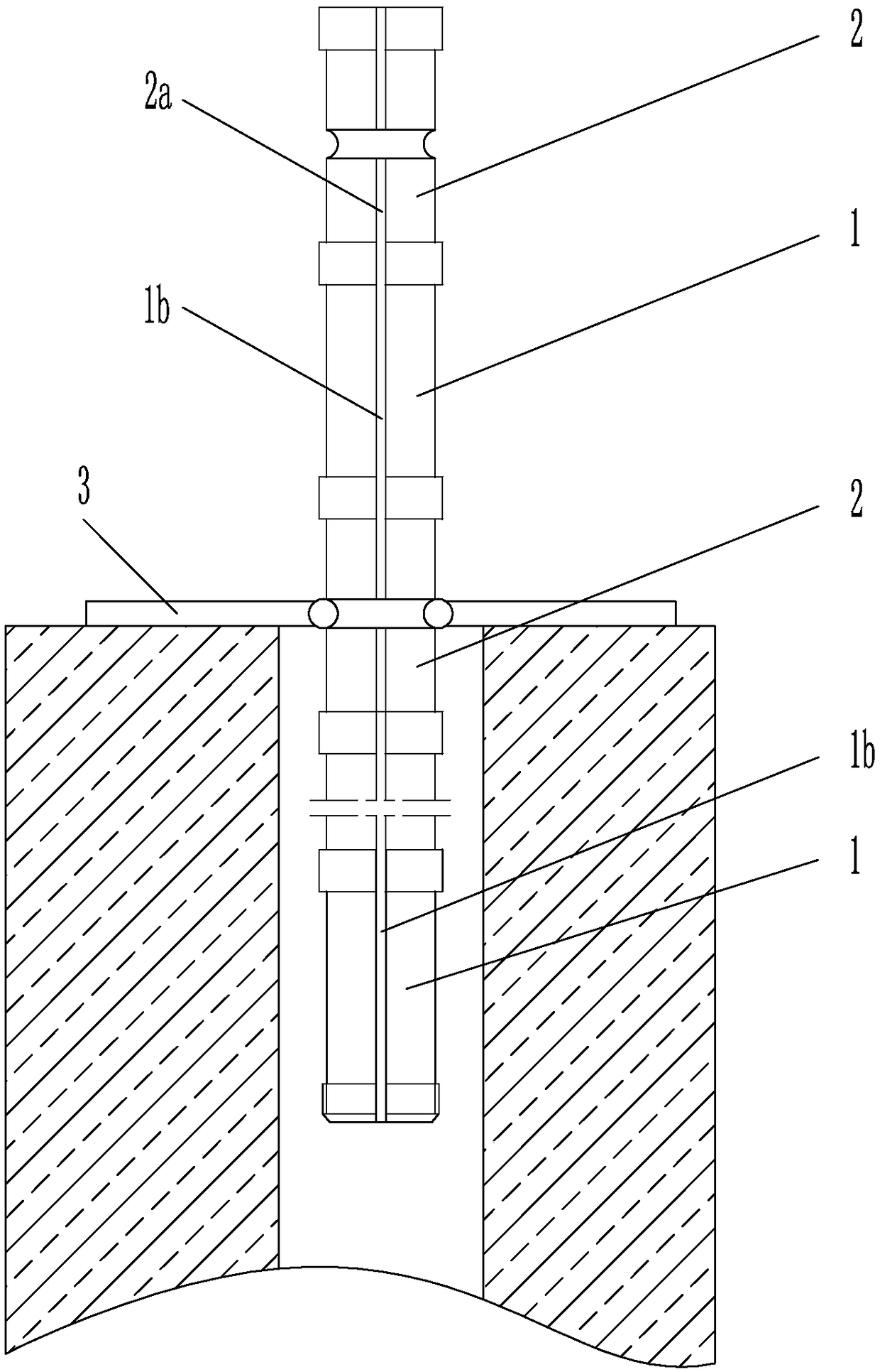
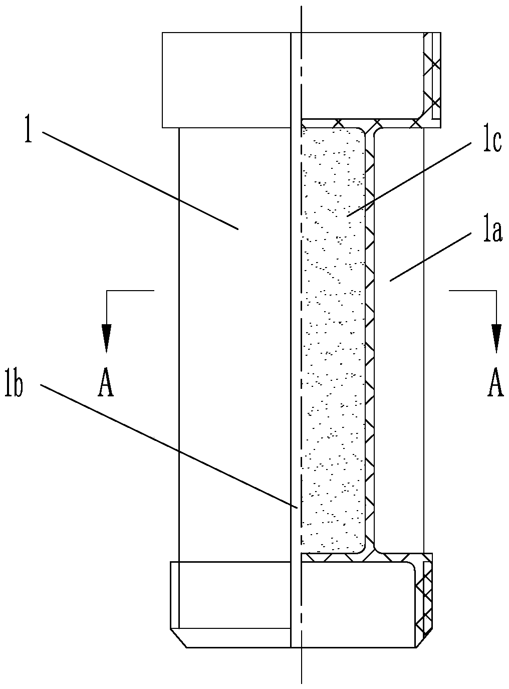
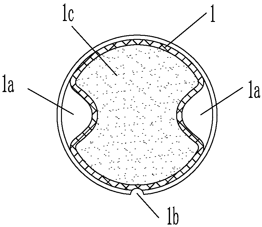
[0030] Example 1, see figure 1 , figure 2 , image 3 , Figure 4 , a pre-splitting blasting combined charge method for forming at least two charge sections and at least one spacer section in a blasthole, comprising forming at least one shaped charge column 1 into a corresponding charge section; forming at least one shaped spacer The column 2 forms a corresponding spacer section; and, a step of connecting a shaped charge column 1 and a formed spacer column 2 to form a charge section and a spacer section; wherein, the side wall of the shaped charge column 1 is formed with two lines in the shape of 180 The U-shaped energy-gathering groove 1a with a high-degree distribution, the U-shaped energy-gathering groove 1a extends axially along the formed charge 1; the first detonating cord groove 1b is formed between the two U-shaped energy-gathering grooves 1a, and the formed charge 1 passes through The explosive powder column is formed by injection molding; the molded spacer column ...

Embodiment 2

[0034] Embodiment 2, see figure 1 , figure 2 , image 3 , Figure 4 , a combined charge structure for pre-splitting blasting, at least two shaped charge columns 1 and at least one formed spacer column 2 are connected in series to form at least two charge sections and at least one spacer section in the blasthole; the shaped charge column 1 and the formed spacer column 2 both have a circular tank structure; the two ends of the formed drug column 1 and the formed spacer column 2 are respectively formed with internal and external threads of the same specification; the middle part of the tank wall of the formed spacer column 2 is formed with an annular groove 2b.

[0035] Wherein, the shaped charge 1 is formed by injecting and encapsulating the explosive charge; two U-shaped energy-gathering grooves 1a distributed at 180 degrees are formed on the side wall of the shaped charge 1, and the U-shaped energy-gathering grooves 1a along the The shaped charge 1 extends axially; a firs...

Embodiment 3

[0036] Embodiment 3, see Figure 5 , an auxiliary device 3 for pre-splitting blasting combined charges, including a C-shaped caliper 3a, and at least three handles 3b are fixedly connected radially on the C-shaped caliper 3a. In this embodiment, there are four, C-shaped The diameter of the caliper 3a matches the annular groove 2b on the formed spacer column 2 described in Embodiment 1 or Embodiment 2.

[0037] Wherein, the C-shaped caliper 3a and the handle 3b are both made of synthetic plastics, and the synthetic plastics are composed of the following components, wherein 60-90 parts of PA plastic nylon particles, 3-10 parts of carbon fiber particles, ultra-high molecular weight 10-20 parts of polyethylene fiber filaments, 2-5 parts of lubricant.

[0038] The following introduces the practical application of applying the method of embodiment 1 and the auxiliary device 3 of embodiment 3 to form the combined charge structure of embodiment 2 in the blast hole.

[0039] Case 1. ...


PUM


Abstract

The invention discloses a pre-split blasting combined explosive charging method, an explosive charging structure and an auxiliary device. The combined explosive charging method is characterized in that forming grains and forming spacer columns are combined through screwing connection, and are supported at the auxiliary device at an opening of a blast hole, so that the forming spacer columns are supported at the opening of the blast hole, then the forming spacer columns form a connection foundation, and then at least two explosive charging sections and at least one spacing section are formed inthe blast hole; the explosive charging structure is composed of the forming grains and the forming spacer columns, moreover, energy gathering grooves are formed in the forming grains, detonating cordgrooves are formed in the forming grains and the forming spacer columns, and the inner threads and the outer threads with the same specification are correspondingly arranged at the two ends of the forming grains and the two ends of the forming spacer columns, so that an explosive charging module is formed; and the auxiliary device is used for supporting the forming spacer columns with the annulargrooves in the middles in the opening of the blast hole so as to form the follow-up explosive charging connection foundation. The pre-split blasting combined explosive charging method, the explosivecharging structure and the auxiliary device have the beneficial effects that the explosive charging method can effectively recue the labor intensity, save the labor and improve the efficiency; and theauxiliary device for the explosive charging structure provides a guarantee for achieving modular explosive charging.

Description

technical field [0001] The invention relates to pre-splitting blasting in open-air step blasting, in particular to a combined charging method, charging structure and auxiliary device for pre-splitting blasting. Background technique [0002] Pre-splitting blasting is a controlled blasting technology commonly used in open-air step blasting to form a contour or slope; in order to protect the retained rock mass and form a flat slope surface, pre-splitting blasting generally uses special low-power explosives or uncoupled charges. Realization, usually adopts uncoupled charge structure. Uncoupled charges are divided into radial uncoupled and axial uncoupled charges. Compared with ordinary charges, uncoupled charges, especially axial uncoupled charges, are much more cumbersome in construction. At the same time, due to human operation, There are often certain errors in the interval charging, and the interval distance cannot be accurately controlled, resulting in unsatisfactory blast...

Claims


Application Information

Patent Timeline
Patent Type & Authority Applications(China)
IPC IPC(8): F42D1/08F42D3/04
CPCF42D1/08F42D3/04
Inventor 朱宽黄雄
Owner CHINA GEZHOUBA GRP YIPULI CO LTD
Why Eureka
Try Eureka