A Direct Boost Double-fed Switched Reluctance Generator Converter System

A technology of switched reluctance and generator, which is applied in the direction of controlling the generator through the change of the magnetic field, controlling the generator, and controlling the system. The effect of low weight cost

Active Publication Date: 2021-02-12
CHINA JILIANG UNIV
View PDF7 Cites 0 Cited by
  • Summary
  • Abstract
  • Description
  • Claims
  • Application Information

AI Technical Summary

Problems solved by technology

[0003] The structure of the switched reluctance generator body is extremely simple and strong, and the cost is also low. It should have a wide range of application prospects, but its current conversion is more complicated. According to the real-time position information of the rotor, each phase winding needs to be divided into at least excitation and power generation. At present, under the premise of improving stability, improving the utilization rate of the inverter structure, simplifying the conversion process, regenerating electric energy, and intelligentization are the development trends.

Method used


Image

  • A Direct Boost Double-fed Switched Reluctance Generator Converter System

Examples


Embodiment Construction

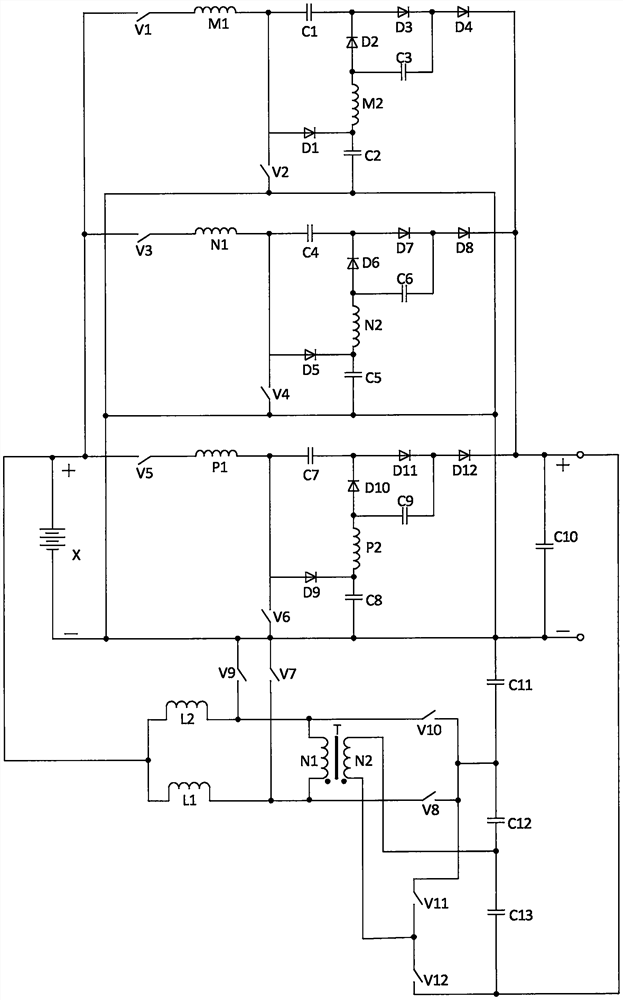
[0021] In this embodiment, a direct-boost double-fed switched reluctance generator converter system, the circuit structure of the converter system is as follows figure 1As shown, it consists of battery X, first switch tube V1, second switch tube V2, third switch tube V3, fourth switch tube V4, fifth switch tube V5, sixth switch tube V6, seventh switch tube V7, The eighth switching tube V8, the ninth switching tube V9, the tenth switching tube V10, the eleventh switching tube V11, the twelfth switching tube V12, the first winding M1 of the first phase winding, the second winding of the first phase winding M2, the first branch winding N1 of the second phase winding, the second branch winding N2 of the second phase winding, the first branch winding P1 of the third phase winding, the second branch winding P2 of the third phase winding, the first capacitor C1, the second capacitor C2, the third capacitor C3, the fourth capacitor C4, the fifth capacitor C5, the sixth capacitor C6, t...


PUM


Abstract

A direct-boost double-fed switched reluctance generator converter system, structurally composed of a battery, twelve switch tubes, three-phase windings, thirteen capacitors, twelve diodes, a transformer, and two inductors, each proposed The two branch windings of the phase winding are respectively excited by different excitation power sources and control modes, and obtain enhanced excitation effects. Under the self-excitation power generation structure, high voltage can be directly output, which adapts to the demand for high voltage in most occasions and reduces links. At the same time, this structure reserves a mode that is suitable for the continuous current of the phase winding current in the whole domain, which has strong adaptability, the battery is automatically charged and has high quality, and at the same time, it can feed back energy, so that the power generation system can work normally under extreme conditions on the load side and help the load side to ride through faults. Based on the above functions, the whole system realizes common ground and no power frequency transformer; the invention is applicable to the application field of all kinds of small and medium power high-speed switched reluctance generator systems with various power input and output sides as loads or power grids.

Description

technical field [0001] The present invention relates to the field of switched reluctance motor systems, in particular to a system that directly raises the output voltage of power generation, bidirectionally feeds energy between the excitation power supply and the output end of the power generation, and has high forward charging quality, can strengthen the excitation, share the ground of the whole system, and can adapt to the whole field of phase windings. A current continuous switched reluctance generator converter system and a control method thereof. Background technique [0002] The application of switched reluctance generators is relatively late, and its research and development are relatively slow in recent years. The key lies in the constraints of its converter system, which specifically involves the improvement of power generation efficiency and benefits, the cost performance of the converter system structure, and the control of converters. Ease of implementation, and ...

Claims


Application Information

Patent Timeline
Patent Type & Authority Patents(China)
IPC IPC(8): H02P9/30H02P9/38H02P9/00H02J7/00
CPCH02J7/0068H02P9/00H02P9/30H02P9/38
Inventor 孙冠群吴懂健郭倩
Owner CHINA JILIANG UNIV
Why Eureka
Try Eureka