Heating cable with temperature and breaking point sensing functions

A technology of sensing function and heating cable, applied in the application of thermometer, shape of thermometer, heating element, etc., can solve the problems of low accuracy of optical fiber acquisition temperature, high cost of additional construction, high cost of temperature sensing, etc., and achieve low maintenance cost. , The effect of low construction cost and accurate temperature data

Active Publication Date: 2018-12-21
智云安科技(北京)有限公司
View PDF5 Cites 4 Cited by
  • Summary
  • Abstract
  • Description
  • Claims
  • Application Information

AI Technical Summary

Problems solved by technology

It is very inconvenient to install sensors outside the heating pipe, and the additional construction cost is high; the cost of distributed temperature sensing by laying optical fibers is high, and in the working range of 20-60 degrees, the accuracy of optical fiber acquisition temperature is lower than conventional Temperature Sensor

Method used


Image

  • Heating cable with temperature and breaking point sensing functions

Examples


Embodiment Construction

[0041] Below in conjunction with accompanying drawing, technical scheme of the present invention is described in further detail:

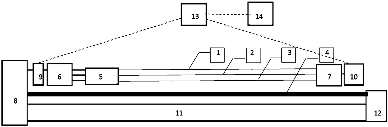
[0042] When producing cables, sensor modules 5 are arranged equidistantly on the main cable 4 in advance. The sensor modules 5 are driven by the positive power line 1 and the negative power line 3 and communicate with the communication master controller through the data bus 2 . The main communication controller 6 is connected with the wireless transceiver 9 of the main controller, and communicates with the cloud server 13 through the wireless transceiver 9; Communicate with cloud server 13. The cloud server 13 collects and stores the data collected by the sensor modules 5 distributed on the cables, and combines the data of the heat tracing control system 8 for calculation and analysis. Through the user browser 14, the user can view the operating status, fault prompt and breakpoint position display of the cable system. Among them, the positive pow...


PUM


Abstract

The invention discloses an intelligent heating cable system which can position a breaking point of a cable and senses a cable temperature. The cable system can achieve breaking point sensing and temperature control functions with low cost, and is subjected to modular design so as to facilitate later maintenance and management.

Description

technical field [0001] The invention relates to a smart cable, in particular to a smart heating cable capable of locating the breaking point of the cable and sensing the temperature of the cable. Background technique [0002] In the electric heat tracing technology of oil and gas pipelines, it is necessary to monitor the temperature of cables. The traditional technology collects temperature information by adding sensors outside the heating tube or through optical fibers. It is very inconvenient to install sensors outside the heating pipe, and the cost of additional construction is high; the cost of distributed temperature sensing by laying out optical fibers is high, and in the working range of 20-60 degrees, the accuracy of optical fiber acquisition temperature is lower than conventional Temperature Sensor. [0003] In the invention, the sensors are equidistantly arranged on the cable, and the wireless module is used for control, thereby reducing the construction and main...

Claims


Application Information

Patent Timeline
Patent Type & Authority Applications(China)
IPC IPC(8): G01K13/00G01R31/02G08C17/02G08C19/00H05B3/56G01K1/024
CPCH05B3/56G08C17/02G08C19/00G01K13/00G01R31/58G01R31/50
Inventor 翁志良贾开明
Owner 智云安科技(北京)有限公司
Why Eureka
Try Eureka