
Accurate simulation device and method of radar target distance for linear frequency modulation signal

A chirp signal and radar target technology, applied in radio wave measurement systems, instruments, etc., can solve the problems that the processor speed cannot keep up with the sampling speed, the length of the optical fiber delay line is limited, the simulation accuracy is limited, etc., and achieves strong universality. The effect of high reliability and maintainability, low cost and high flexibility

Active Publication Date: 2018-12-21
THE 41ST INST OF CHINA ELECTRONICS TECH GRP
View PDF8 Cites 20 Cited by
  • Summary
  • Abstract
  • Description
  • Claims
  • Application Information

AI Technical Summary

Problems solved by technology

[0004] 1. Due to the high-speed data acquisition and storage technology, the sampling accuracy is related to the processing speed of the processor. At present, the final simulation accuracy is limited because the processor speed cannot keep up with the sampling speed.
[0005] 2. Due to the use of large-capacity memory for data caching, the larger the memory capacity, the longer the simulation distance. At present, even if the most advanced DDR memory is used, the stored data capacity is limited, and it can only simulate a distance of tens of meters at most, so This method can only perform short-distance simulations, and the length of the fiber delay line used in long-distance simulations will also be limited, resulting in a limited final simulation distance
[0006] 3. In the existing radar target distance simulation method for chirp signals, the method of large-capacity storage + delay line is often used for target distance simulation, which eventually leads to large simulator size and high cost

Method used


Image

  • Accurate simulation device and method of radar target distance for linear frequency modulation signal
  • Accurate simulation device and method of radar target distance for linear frequency modulation signal
  • Accurate simulation device and method of radar target distance for linear frequency modulation signal

Examples


Embodiment Construction

[0071] It should be pointed out that the following detailed description is exemplary and intended to provide further explanation to the present application. Unless defined otherwise, all technical and scientific terms used herein have the same meaning as commonly understood by one of ordinary skill in the art to which this application belongs.

[0072] It should be noted that the terminology used here is only for describing specific implementations, and is not intended to limit the exemplary implementations according to the present application. As used herein, unless the context clearly dictates otherwise, the singular is intended to include the plural, and it should also be understood that when the terms "comprising" and / or "comprising" are used in this specification, they mean There are features, steps, operations, means, components and / or combinations thereof.

[0073] As introduced in the background art, traditional simulation devices and methods have the following disadv...


PUM


Abstract

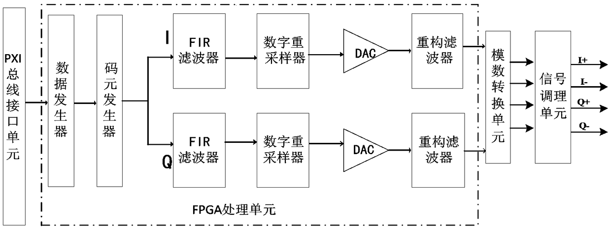
The invention relates to an accurate simulation device and method of a radar target distance for a linear frequency modulation signal. The accurate simulation device is composed of a down conversion unit, an intermediate-frequency amplification unit and a delay unit. The down conversion unit is formed by a millimeter-wave down converter module and is used for converting a received millimeter-waveradar signal into an intermediate-frequency signal for post-stage processing. The intermediate-frequency amplification unit consists of a PXI bus programmable amplifier module and is used for amplifying an intermediate frequency signal amplitude after down conversion and carrying out adjustment based on different gain needs. The delay unit is composed of a baseband generating module, an I / Q modulator, and a power control module and is used for modulating a baseband signal to a carrier signal and carrying out amplitude control on the modulated signal. The baseband signal is used as the modulation signal, the received radar linear frequency modulation signal is used as the carrier signal for frequency modulation, and the frequency information set by the baseband signal reflects the distanceof the target. The method is implemented based on the idea of frequency modulation; and simulation of the radar target distance is realized.

Description

technical field [0001] The invention belongs to the technical field of radio frequency microwave testing, in particular to a device and method for accurately simulating a radar target distance of a linear frequency modulation signal. Background technique [0002] The traditional linear frequency modulation signal radar target distance simulation device is mainly composed of a down-conversion unit, an intermediate frequency amplification unit, a delay unit, and an up-conversion unit. , and then collect the intermediate frequency signal, store the data, convert D / A, and process the frequency up conversion to obtain the echo signal. [0003] The existing device and method for simulating the radar target distance of the chirp signal have the following deficiencies: [0004] 1. Due to the high-speed data acquisition and storage technology, the sampling accuracy is related to the processing speed of the processor. At present, the final simulation accuracy is limited because the p...

Claims


Application Information

Patent Timeline
Patent Type & Authority Applications(China)
IPC IPC(8): G01S7/40
CPCG01S7/4056
Inventor 刘军智张光山王盘伟郭利强钱时祥
Owner THE 41ST INST OF CHINA ELECTRONICS TECH GRP
Learn More