Control system and dynamic positioning method of underwater auxiliary oil recovery robot

A control system and dynamic positioning technology, applied in the field of robotics, can solve the problems of lack of underwater light irradiation and camera shooting, low dynamic positioning accuracy, and no consideration of the complexity of ocean conditions, so as to improve accuracy, ensure positioning accuracy, and be good Anti-interference effect

Active Publication Date: 2021-05-04
JIANGSU UNIV OF SCI & TECH
View PDF12 Cites 0 Cited by
  • Summary
  • Abstract
  • Description
  • Claims
  • Application Information

AI Technical Summary

Problems solved by technology

The application number is "201510107334.3", and the patent document titled "A Water Surface Control Device for an Underwater Robot" does not take into account the preservation of the video captured by the camera. After the underwater robot experiment is over, it is impossible to analyze the performance of the robot and observe information about underwater life
The application number is "201610952988.0", and the patent document titled "A Submarine Pipeline Inspection Underwater Robot" does not mention the design of underwater lights and underwater cameras in the detection device, and there is no underwater light irradiation and camera shooting. Surface operators cannot manipulate the movement of manipulators and robots according to actual conditions
The application number is "201610124928.X", and the patent document titled "Adaptive filtering method for tracking environmental force mutations in dynamic positioning" does not consider the complexity of the ocean situation and the inaccuracy of the disturbance model, resulting in the accuracy of dynamic positioning. not tall

Method used


Image

  • Control system and dynamic positioning method of underwater auxiliary oil recovery robot
  • Control system and dynamic positioning method of underwater auxiliary oil recovery robot
  • Control system and dynamic positioning method of underwater auxiliary oil recovery robot

Examples


Embodiment Construction

[0098] The present invention will be further described below in conjunction with the accompanying drawings and specific embodiments.

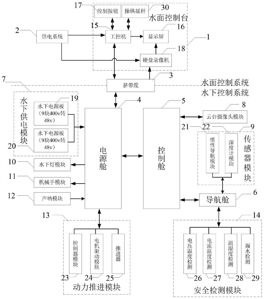
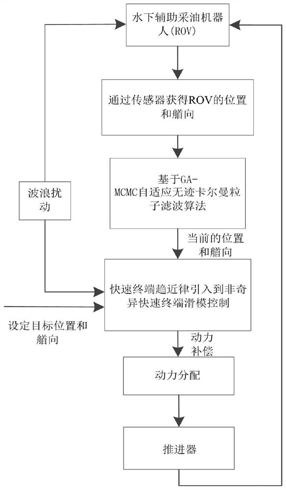
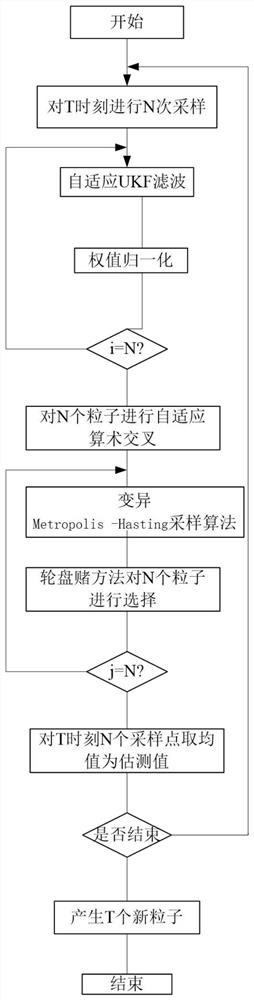
[0099] Such as figure 1 As shown, the underwater auxiliary oil production robot control system includes a water surface control system and an underwater control system. The water surface control system is placed on the shore or on the mother ship, and the underwater control system is installed on the underwater auxiliary oil production robot; The control system includes a surface console 1, a power supply system 2, and an umbilical cable 3. The surface console 1 and the umbilical cable 3 are respectively connected to the power supply system 2 to provide energy and data transmission for the underwater auxiliary oil recovery robot body. The underwater control system The underwater power supply module 7 included in the power supply cabin 4, the underwater light module 10, the manipulator module 11, the sonar module 12, the power propulsion module ...


PUM


Abstract

The invention discloses a control system system and a dynamic positioning method of an underwater auxiliary oil recovery robot. Aiming at the uncertainty problem caused by the movement of the underwater auxiliary oil recovery robot being disturbed by the ocean current, combined with the developed underwater auxiliary oil recovery robot, based on fluid dynamics The dynamic model is established by digital simulation identification parameter method, and the six-degree-of-freedom dynamic positioning analysis is carried out. Obtain the position and heading of the underwater auxiliary oil production robot through the sensor, and use the adaptive unscented Kalman particle filter algorithm based on the genetic algorithm combined with the Markov chain Monte Carlo method to estimate the state of the underwater robot in real time, and the fast terminal approach The law is introduced into the non-singular fast terminal sliding mode control to compensate the thrust, so as to reduce the influence caused by disturbances such as ocean currents, and then design the force and moment distribution strategy according to the positioning error. This method has a good dynamic positioning effect, and can quickly adjust the power distribution strategy after being disturbed to reduce the disturbance caused by random ocean currents.

Description

technical field [0001] The invention relates to an underwater auxiliary oil recovery robot, in particular to a control system and a dynamic positioning method of an underwater auxiliary oil recovery robot, belonging to the technical field of robots. Background technique [0002] The development of offshore oil and gas resources, from exploration, drilling, extraction to crude oil transportation, requires a large number of underwater equipment installation, maintenance and repair tasks, and the underwater operation technology is complex and requires high precision. Underwater oil and gas equipment has the characteristics of high integration, heavy weight, complex structure, and high cost. Unmanned remote operated vehicle (Remote Operated Vehicle, ROV) is one of the essential equipment for underwater operations and emergency maintenance of offshore oil and gas fields. Undertake underwater search and observation, subsea wellhead docking, blowout preventer installation, subsea o...

Claims


Application Information

Patent Timeline
Patent Type & Authority Patents(China)
IPC IPC(8): G05D1/06
CPCG05D1/0692
Inventor 曾庆军周海霞朱志宇张永林陈伟史志晨
Owner JIANGSU UNIV OF SCI & TECH
Why Eureka
Try Eureka