

A flat filament for an X-ray CT tube
An X-ray and flat-panel technology, which is applied to X-ray tube components, X-ray tube electrodes, X-ray tube cathode components, etc.
- Summary
- Abstract
- Description
- Claims
- Application Information
AI Technical Summary
Problems solved by technology
Method used
Image

Examples
Embodiment 1
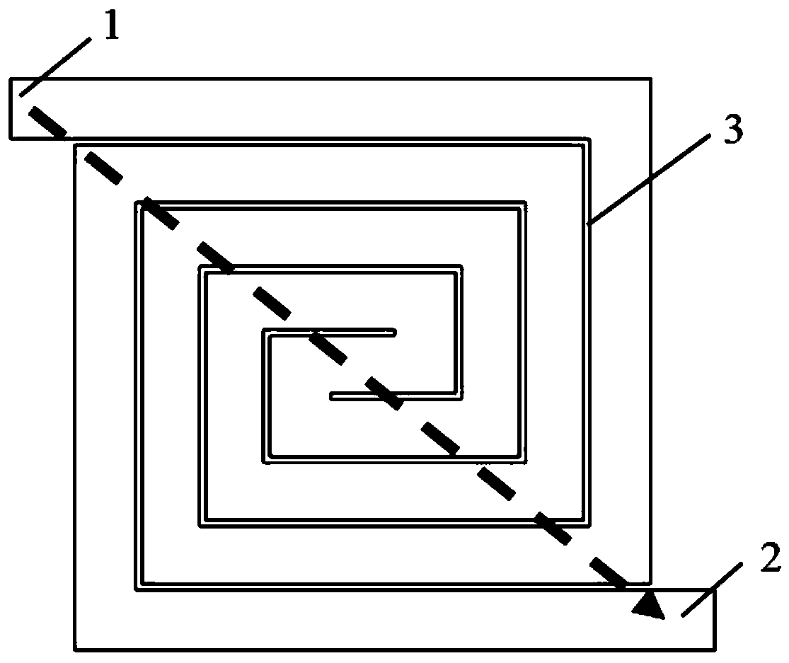
[0030] Embodiment 1 provides a flat filament used in an X-ray CT tube for generating directional electron beams, and its structural schematic diagram is shown in FIG. 2( a ). The flat plate filament for X-ray CT tube includes a flat plate and an emitting structure formed on the flat plate. The emission structure is a square ring structure formed by a plurality of slots. Wherein, the thickness of the flat plate is 0.05-0.3 mm.
[0031] Specifically, the emission structure is composed of a plurality of "bow"-shaped units, and the plurality of "bow"-shaped units are connected to form a square ring structure as shown in Figure 2(a). The emission structure adopts four pins, which makes the flat filament structure more stable.
[0032] The four pins are respectively a first pin 21 , a second pin 22 , a third pin 23 and a fourth pin 24 . The opposite two pins are both current output terminals, or both are current input terminals; one of the two adjacent pins is the current output ...
Embodiment 2
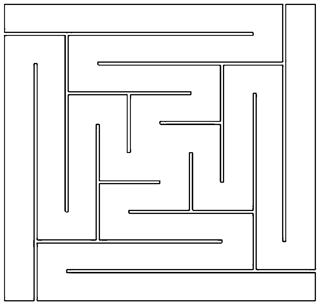
[0037] As shown in FIG. 3( a ), it is a flat filament for an X-ray CT tube provided in the second embodiment. The flat plate filament for X-ray CT tube includes a flat plate and an emitting structure formed on the flat plate. The difference from Embodiment 1 is that the emission structure is a square strip structure formed by a plurality of through grooves. Wherein, the thickness of the flat plate is 0.05-0.3 mm.
[0038] Specifically, the emission structure is composed of a plurality of "bow"-shaped units, and the plurality of "bow"-shaped units are connected to form a square strip structure as shown in Fig. 3(a). The emission structure adopts four pins, which can make the structure of the flat filament more stable, avoid stress deformation of the flat filament due to centrifugal force when the CT machine scans and rotate at high speed, and prolong the service life of the filament.
[0039]Same as the first embodiment, the four pins are the first pin 31 , the second pin 32 ...
Embodiment 3
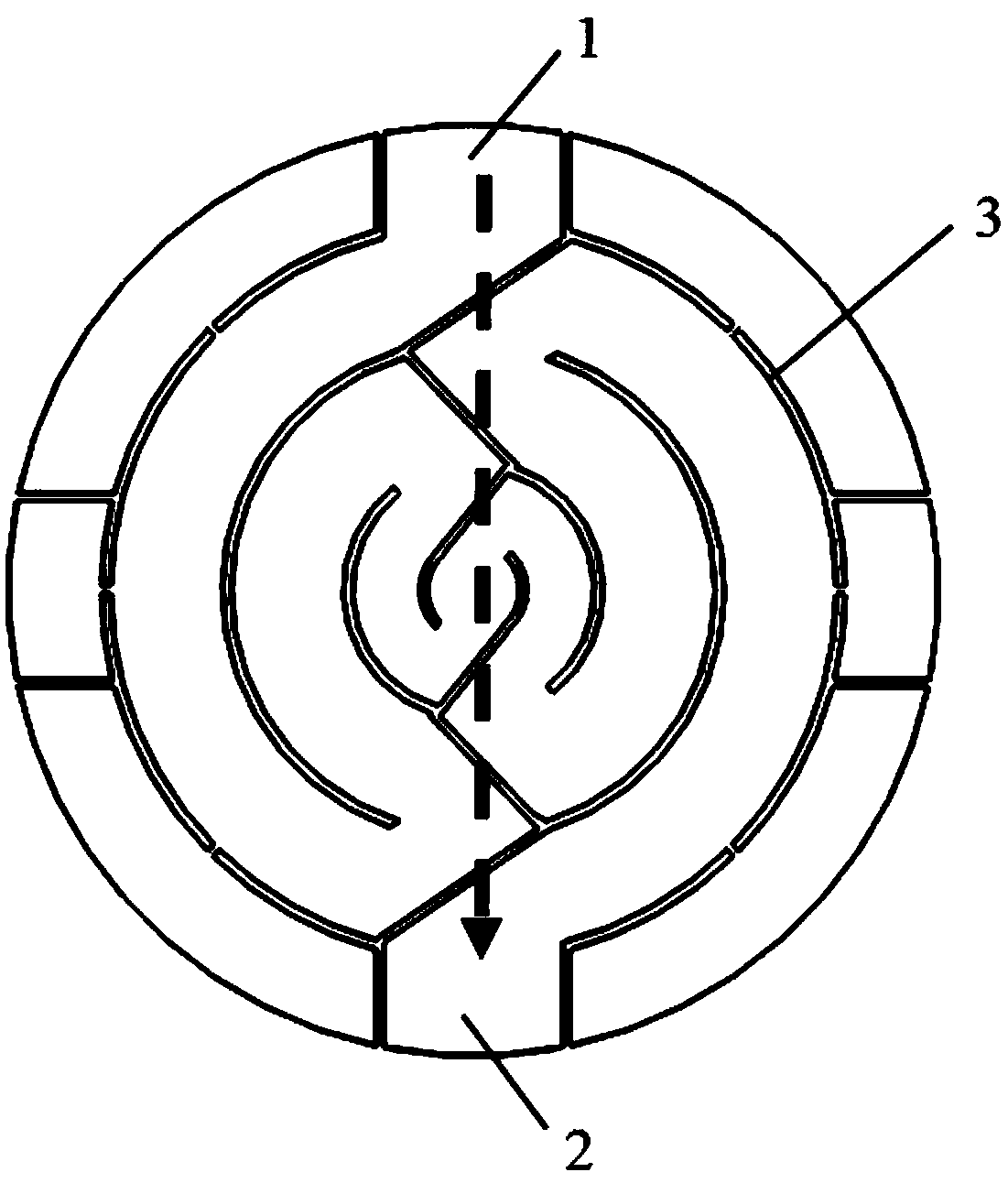
[0044] As shown in FIG. 4( a ), it is a flat filament used in an X-ray CT tube provided by the third embodiment. The flat plate filament for X-ray CT tube includes a flat plate and an emitting structure formed on the flat plate. The difference from Embodiment 1 and Embodiment 2 is that the emission structure is a circular structure formed by a plurality of through grooves. Wherein, the thickness of the flat plate is 0.05-0.3 mm.
[0045] Please refer to Figure 4(a), the through groove is set from the upper end of the plate to the lower end of the plate, from the left end of the plate to the right end of the plate, and multiple bifurcation points are set on the channel path, each bifurcation point One end forms an arc with the center of the flat plate as the center, and the other end leads to the next bifurcation; finally, a rotationally symmetrical network figure with a rotation angle of 90° is formed. The emission structure adopts four pins, which can make the structure of ...
PUM
| Property | Measurement | Unit |
|---|---|---|
| Groove width | aaaaa | aaaaa |
| Thickness | aaaaa | aaaaa |
Abstract
Description
Claims
Application Information