Radome, antenna structure and wireless electronic device

An antenna structure and radome technology, applied in the field of wireless propagation, can solve the problems of high millimeter wave propagation loss and short wireless propagation distance

Active Publication Date: 2018-12-21
VIVO MOBILE COMM CO LTD
View PDF9 Cites 7 Cited by
  • Summary
  • Abstract
  • Description
  • Claims
  • Application Information

AI Technical Summary

Problems solved by technology

[0003] An embodiment of the present invention provides a radome, an antenna structure, and a wireless electronic device to solve the problem in the prior art that the

Method used


Image

  • Radome, antenna structure and wireless electronic device
  • Radome, antenna structure and wireless electronic device
  • Radome, antenna structure and wireless electronic device

Examples


Embodiment Construction

[0017] The following will clearly and completely describe the technical solutions in the embodiments of the present invention with reference to the accompanying drawings in the embodiments of the present invention. Obviously, the described embodiments are some of the embodiments of the present invention, but not all of them. Based on the embodiments of the present invention, all other embodiments obtained by persons of ordinary skill in the art without creative efforts fall within the protection scope of the present invention.

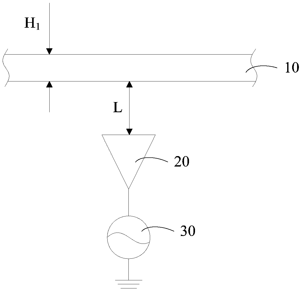
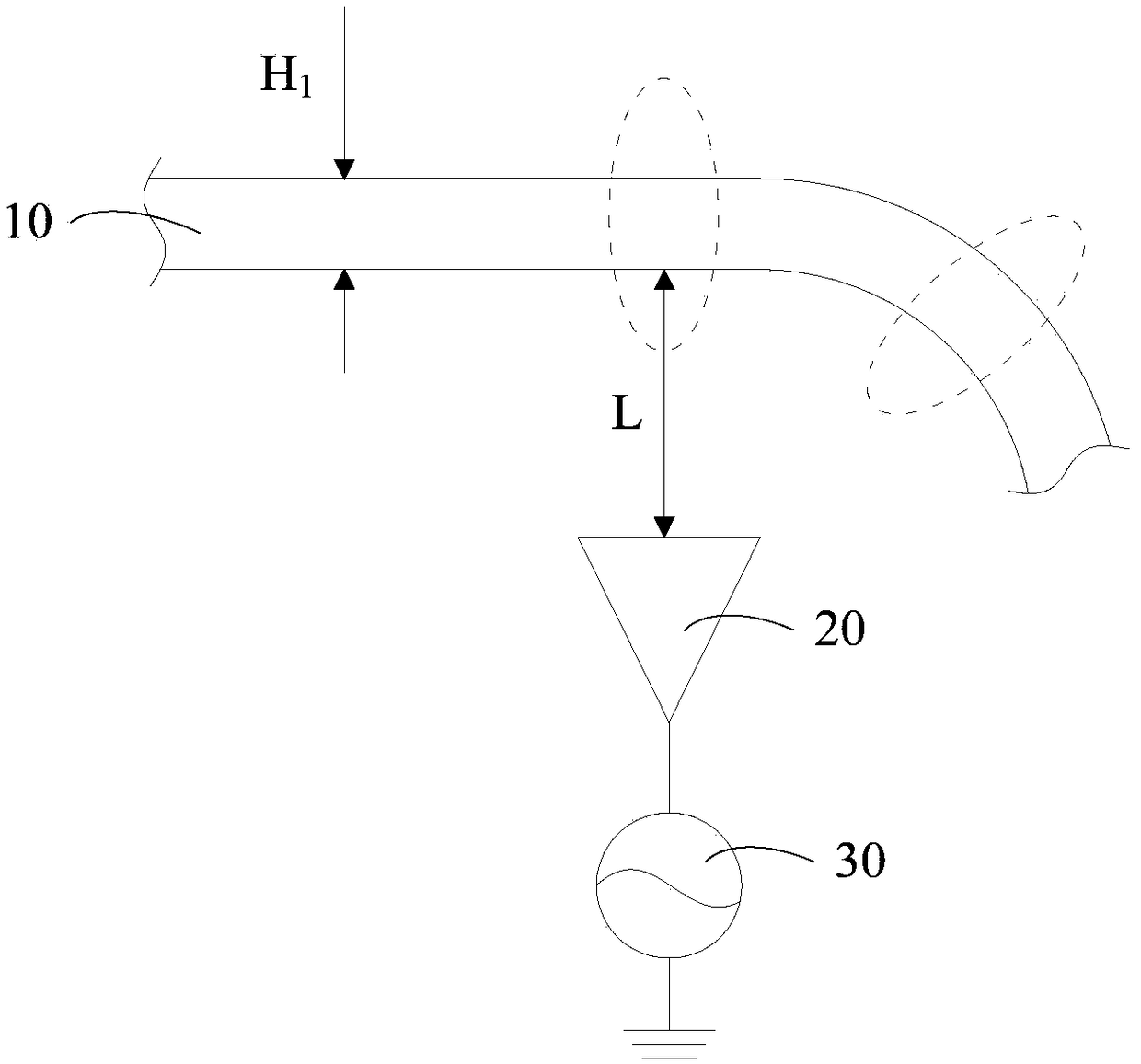
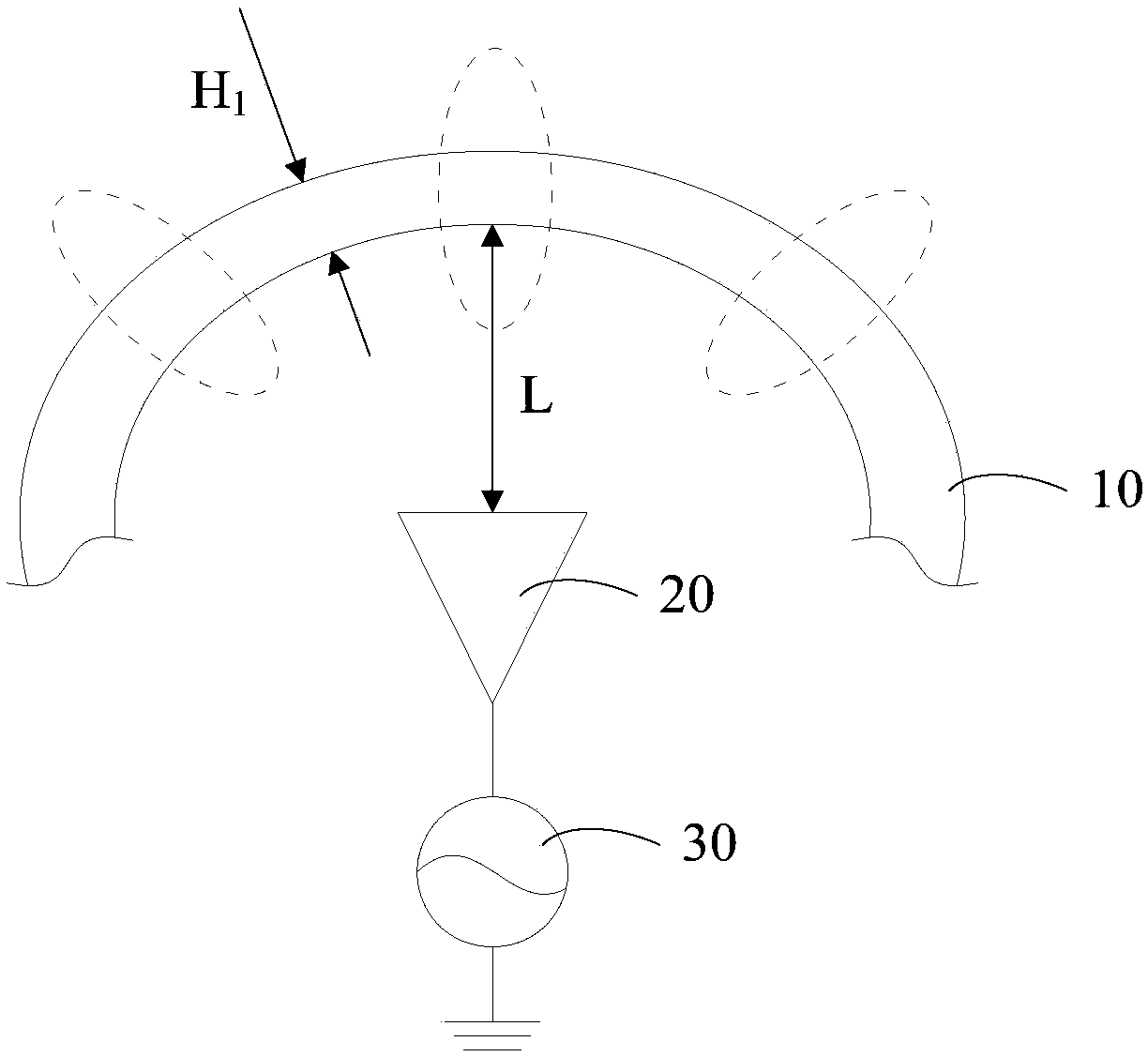
[0018] Such as figure 1 As shown, the embodiment of the present invention provides an antenna structure, including:

[0019] Radome 10;

[0020] And, the radiator 20 located inside the radome 10;

[0021] Among them, (n-1)*λ 1 / 21 1 / 2, the H 1 represents the thickness of the radome 10, the λ 1 Indicates the propagation wavelength of the electromagnetic wave emitted by the radiator 20 in the radome 10, n is a positive integer;

[0022] And / or, L=...


PUM


Abstract

The invention provides a radome, an antenna structure and a wireless electronic device. The antenna structure comprises a radome and a radiator located inside the radome; Where (n-1) *[Lamda]1/2 (H1 (n*[lamda]1/2, H1 denotes the thickness of the radome,[Lamda]1 denotes the propagation wavelength of the electromagnetic wave emitted by the radiator in the radome, and n is a positive integer; And/or,L=a*b*[lambda]0, L denotes the length of the line segment from the radiation surface of the radiator to the inner side of the radome, the centerline being a straight line perpendicular to the radiation surface of the radiator, [lambda]0 denotes the propagation wavelength of electromagnetic waves emitted from the radiator in air, a denotes a preset parameter, and b is a positive integer. In this way, the directivity and gain effect of the electromagnetic wave beam can be enhanced, so as to compensate the loss of the electromagnetic wave in the wireless transmission and achieve a longer wireless transmission distance, thereby improving the overall performance of the antenna structure, reducing the area, circuit complexity and corresponding cost required by the conventional design, and enhancing the overall competitiveness of the product.

Description

technical field [0001] The invention relates to the field of wireless propagation technology, in particular to a radome, an antenna structure and wireless electronic equipment. Background technique [0002] Due to the high-speed data transmission capability and high image resolution due to the large bandwidth of the millimeter wave, the application of the millimeter wave is becoming more and more popular and important. However, due to the high operating frequency of the millimeter wave, the propagation loss of the millimeter wave is relatively high during the wireless transmission process, and the wireless propagation distance is short. Therefore, the actual application needs to be presented in an array to achieve a higher antenna gain. To overcome the high propagation loss and achieve a longer propagation distance. In addition, in order to achieve the best imaging effect, it is often presented in the form of a millimeter-wave antenna array in practical applications to impr...

Claims


Application Information

Patent Timeline
IPC IPC(8): H01Q1/42H01Q21/29
CPCH01Q1/42H01Q21/29
Inventor 黄奂衢王义金简宪静
Owner VIVO MOBILE COMM CO LTD
Why Eureka
Try Eureka