Camshaft adjustment system with hydraulic medium return device

A technology of camshaft adjustment and camshaft adjuster, which is applied in the direction of engine components, machines/engines, fluid pressure actuators, etc., and can solve the problem of high inertia

Active Publication Date: 2021-04-27
SCHAEFFLER TECH AG & CO KG
View PDF1 Cites 0 Cited by
  • Summary
  • Abstract
  • Description
  • Claims
  • Application Information

AI Technical Summary

Problems solved by technology

Furthermore, due to such a long transport system, the inertia of the system is relatively high

Method used


Image

  • Camshaft adjustment system with hydraulic medium return device
  • Camshaft adjustment system with hydraulic medium return device
  • Camshaft adjustment system with hydraulic medium return device

Examples


Embodiment Construction

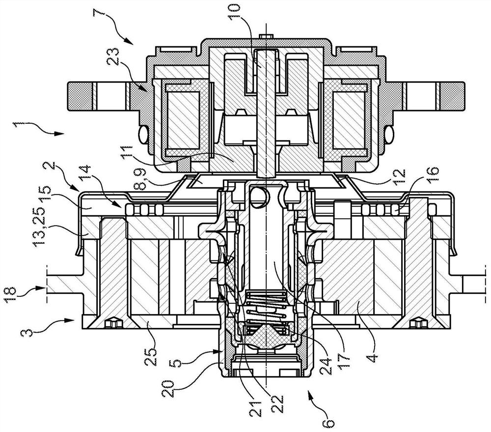
[0027] exist figure 1 A camshaft adjustment system 1 according to a first preferred embodiment is shown schematically in . The camshaft adjustment system 1 is formed from a camshaft adjuster 2 and an actuator 7 acting on the camshaft adjuster 2 in an adjusting manner.

[0028] The camshaft adjuster 2 is basically embodied here as a hydraulic camshaft adjuster 2 . The camshaft adjuster 2 is designed according to the vane unit type / vane unit design. Correspondingly, camshaft adjuster 2 has an outer component referred to as stator 3 . The stator 3 is connected in a rotationally fixed manner to the traction means, ie the chain, of the traction means transmission via the traction means receptacle 18 during operation of the internal combustion engine, the traction means being connected in a conventional manner to the crankshaft of the internal combustion engine in a non-rotatable manner. The traction means receptacle 18 is also referred to as a drive wheel.

[0029] On its radia...


PUM


Abstract

The invention relates to a camshaft adjustment system (1) for an internal combustion engine of a motor vehicle, with a hydraulic camshaft adjuster (2) having a stator (3) supported in a torsion manner on the stator ( 3) the rotor (4) and the hydraulic control system (6) including the valve (5), wherein the rotor (4) has at least one vane that extends into the gap formed between the rotor (4) and the stator (3) In the pressure chamber, so that the pressure chamber is divided into two sub-chambers, where each sub-chamber cooperates with the hydraulic control system (6) to adjust the preset rotor between the two sub-chambers ( 4) hydraulic pressure ratio to the relative rotational position between the stator (3); the camshaft adjustment system also has an actuator (7) arranged adjacently in the axial direction of the camshaft adjuster (2), It acts regulatingly on the valve (5), wherein on the side of the actuator (7) facing the camshaft adjuster (2) a hydraulic medium guide section (8) is arranged, the hydraulic medium The guide section (8) is designed in such a way that it redirects the flow of hydraulic medium escaping from the valve (5) into the surroundings of the camshaft adjuster (2) in the operating state back to the camshaft adjuster (2).

Description

technical field [0001] The invention relates to a camshaft adjustment system for an internal combustion engine, for example a diesel or gasoline engine, of a motor vehicle, such as a passenger car, a van, a bus or an agricultural commercial vehicle, with a hydraulic camshaft adjuster (of the vane unit type), which Hydraulic camshaft adjuster with a stator, a rotor torsionally mounted / accommodated in the stator and a hydraulic control system including valves, wherein the rotor has at least one vane which protrudes into a pressure chamber formed between the rotor and the stator , so that the pressure chamber is divided into two sub-chambers, wherein each sub-chamber cooperates / connects with the hydraulic control system, thereby adjusting the relative rotation between the preset rotor and the stator between the two sub-chambers according to the position of the valve The hydraulic pressure ratio of the position; the camshaft adjustment system also has an actuator arranged adjacent...

Claims


Application Information

Patent Timeline
Patent Type & Authority Patents(China)
IPC IPC(8): F01L1/344
CPCF01L1/3442F01L2001/34423F01L2001/34433F01L2001/34436F01L2001/34483F15B15/12
Inventor 斯特凡·克拉默奥拉夫·伯泽
Owner SCHAEFFLER TECH AG & CO KG
Why Eureka
Try Eureka