
Part drilling equipment for electric sanitation truck production

A technology of drilling equipment and sanitation vehicles, which is applied in the direction of drilling/drilling equipment, boring/drilling, metal processing equipment, etc., which can solve the problem of affecting the normal breathing of the staff, polluting the working environment of the staff, and not collecting debris and other problems, to achieve the effect of good drilling effect, good dust removal effect and high drilling precision

Inactive Publication Date: 2018-12-25
安徽省皖工电动车科技有限公司
View PDF7 Cites 16 Cited by
  • Summary
  • Abstract
  • Description
  • Claims
  • Application Information

AI Technical Summary

Problems solved by technology

When the parts are drilled, more debris will be generated. If the debris floats in the air, it will pollute the working environment of the staff and affect the normal breathing of the staff.
The current part drilling equipment does not collect debris well, which brings great trouble to the staff

Method used


Image

  • Part drilling equipment for electric sanitation truck production
  • Part drilling equipment for electric sanitation truck production
  • Part drilling equipment for electric sanitation truck production

Examples


Embodiment 1

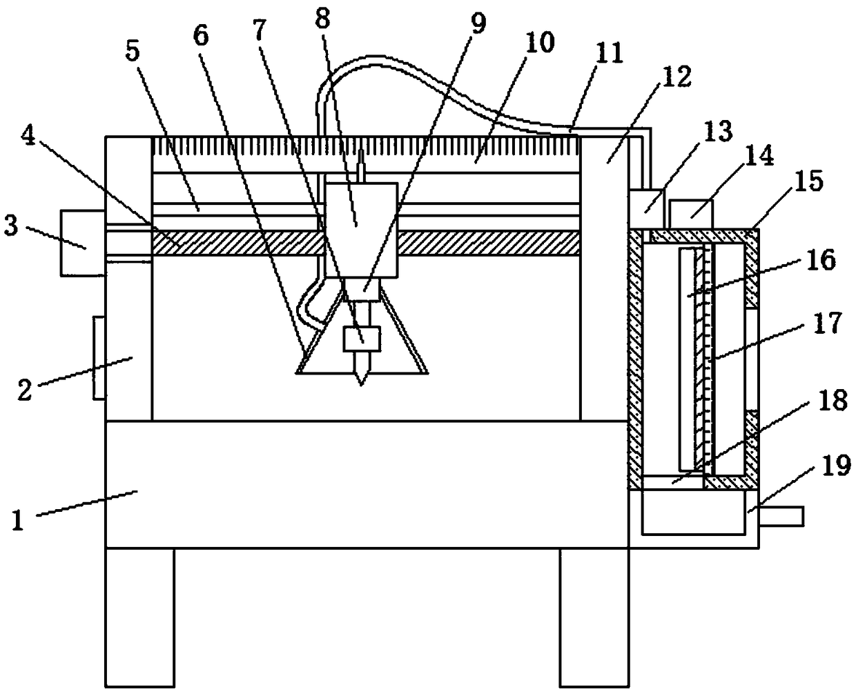
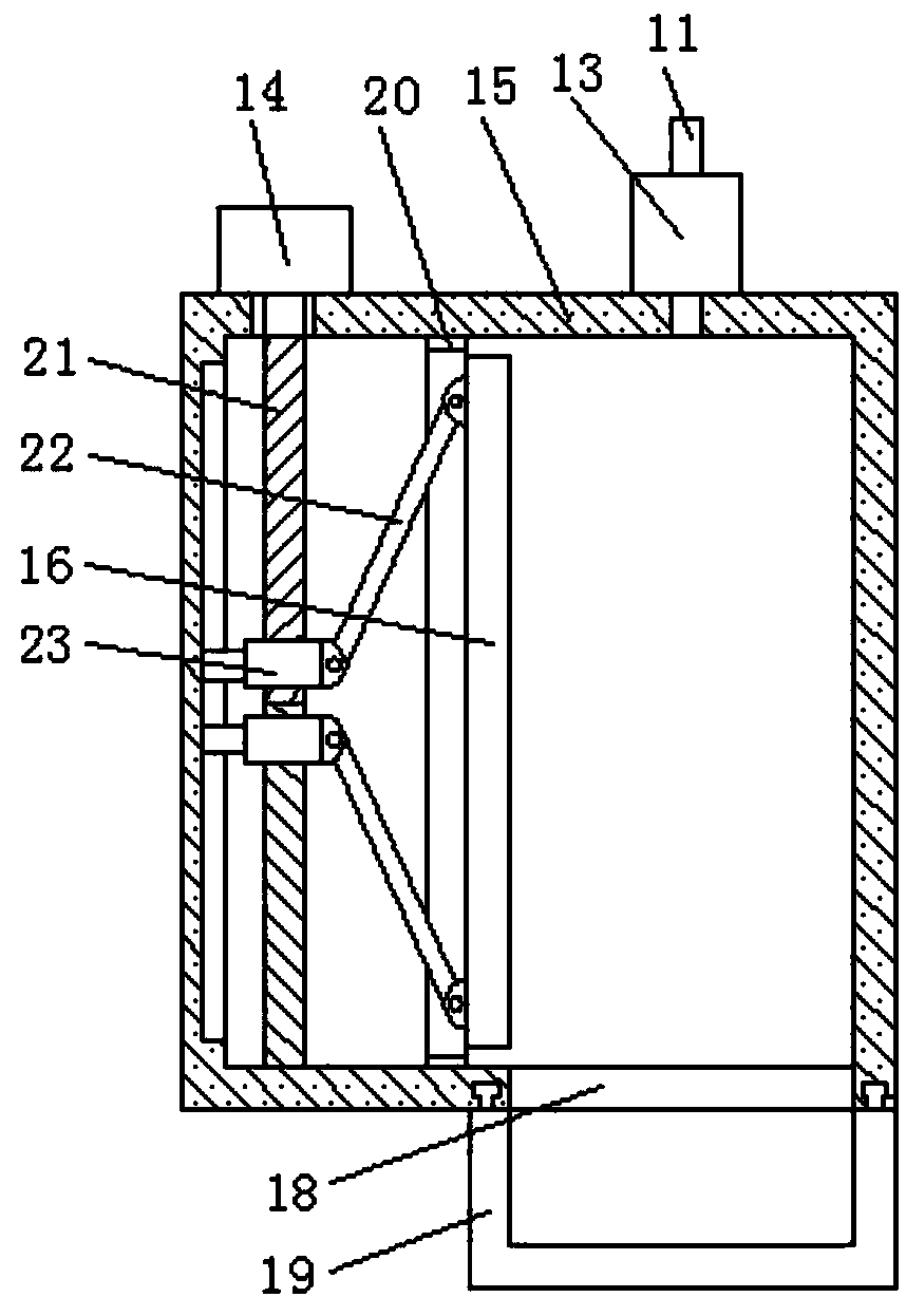
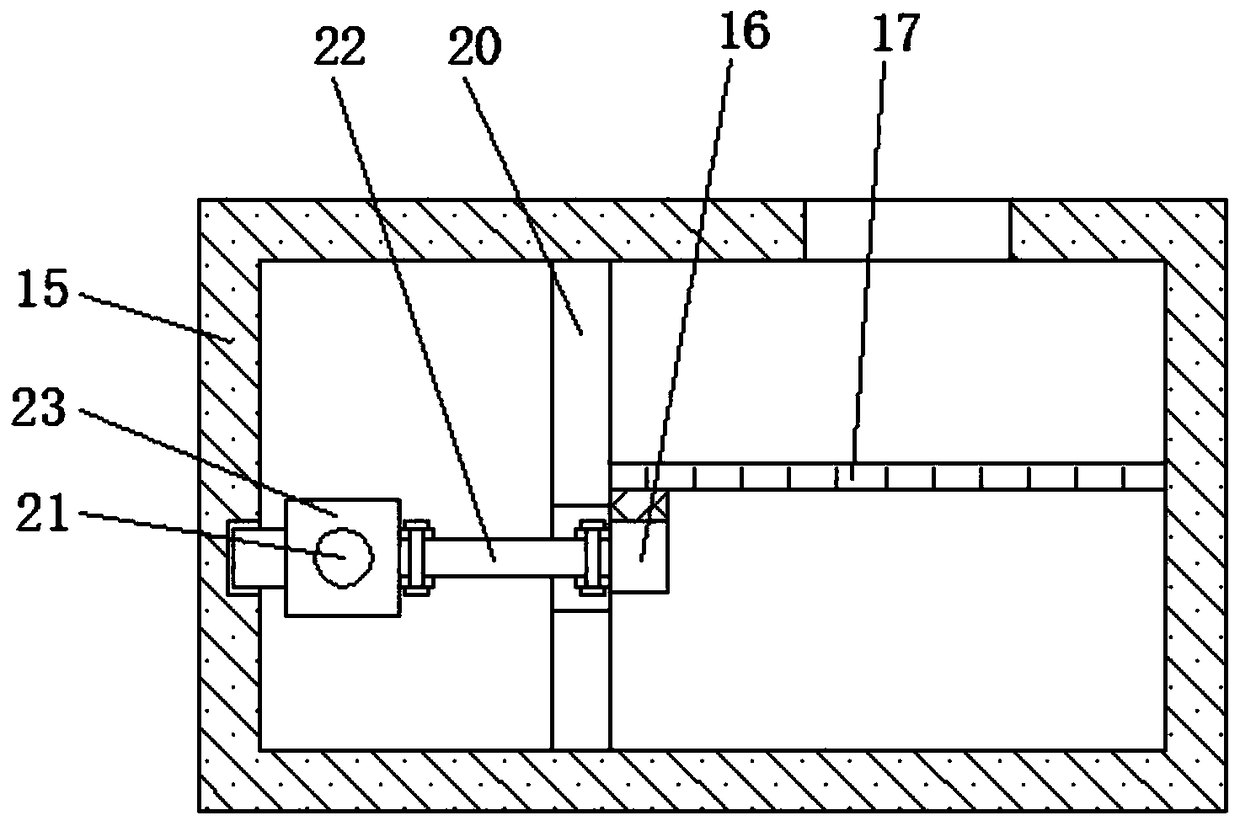
[0024] refer to Figure 1-3 , a kind of parts drilling equipment for the production of electric sanitation vehicles, including a workbench 1, a first side plate 2 and a second side plate 12 are respectively fixed on both sides of the top surface of the workbench 1, and the upper end of the first side plate 2 The first motor 3 is fixed on the side wall of the first motor 3, the output shaft of the first motor 3 is connected with the first lead screw 4, and one end of the first lead screw 4 passes through the first side plate 2 and is connected to the side of the second side plate 12 in rotation. On the wall, the first leading screw 4 is provided with a movable seat 8, the first leading screw 4 is connected with the movable seat 8 by threads, the bottom surface of the movable seat 8 is fixed with a cylinder 9, and the output end of the cylinder 9 is fixed with a second motor 7, The output shaft of the second motor 7 is connected with a drill bit, and a trumpet-shaped dust collec...

Embodiment 2

[0026] Such as Figure 1-3 As shown, this embodiment is basically the same as Embodiment 1. Preferably, a slide bar 5 is provided above the first lead screw 4, and the two ends of the slide bar 5 are respectively fixed on the ends of the first side plate 2 and the second side plate 12. On the side wall, the movable seat 8 is slidably connected to the slide bar 5 .

Embodiment 3

[0028] Such as Figure 1-3 As shown, this embodiment is basically the same as Embodiment 1. Preferably, a scale 10 is provided above the slide bar 5, and the two ends of the scale 10 are respectively fixed on the side walls of the first side plate 2 and the second side plate 12. On, the top of the movable seat 8 is provided with a pointer, and the pointer and the scale 10 cooperate with each other.


PUM


Abstract

The invention discloses part drilling equipment for electric sanitation truck production, and relates to the technical field of the electric sanitation truck production. The part drilling equipment comprises a working table, and a first side plate and a second side plate are separately fixed to two sides of the top surface of the working table. A first motor is fixed to the side wall of the upperend portion of the first side plate, and an output shaft of the first motor is connected with a first lead screw. One end of the first lead screw penetrates through the first side plate to be rotatably connected to the side wall of the second side plate, and the first lead screw is provided with a movable seat. The first lead screw is connected with the movable seat through a thread. A cylinder isfixed to the bottom surface of the movable seat, and a second motor is fixed to the output end of the cylinder. A drill bit is connected to an output shaft of the second motor. The part drilling equipment can collect debris generated during drilling in time, prevents the debris from polluting air and affecting normal breathing of workers, has a good dust removal effect, and can realize effectivepositioning during drilling, so that the position during drilling is accurate, the drilling precision is high, and the drilling effect is good.

Description

technical field [0001] The invention relates to the technical field of production of electric sanitation vehicles, in particular to a part drilling equipment used for the production of electric sanitation vehicles. Background technique [0002] Electric sanitation vehicles are driven by electricity and have the advantages of environmental protection, beauty and reduction of secondary pollution, etc., and are used by relevant sanitation system departments. In addition to being beautiful and adding style to the city appearance, electric sanitation vehicles also reduce labor intensity, save labor costs, and improve work efficiency. In addition, they also realize the low-carbon environmental protection slogan vigorously advocated by the government. [0003] During the production process of electric sanitation vehicles, drilling operations are often required for its parts. When the parts are drilled, more debris will be generated. If the debris is scattered in the air, it will p...

Claims


Application Information

Patent Timeline
IPC IPC(8): B23Q11/00B23Q17/22B23B41/00
CPCB23B41/00B23Q11/00B23Q11/0042B23Q11/0046B23Q17/22
Inventor 张胡记徐长春王和青
Owner 安徽省皖工电动车科技有限公司
Learn More