
H-type vertical axis wind turbine with coaxial jet flow blades

A coaxial jet, vertical axis technology, used in wind turbines, wind turbines at right angles to the wind direction, motors, etc., can solve the problems of large energy input and low application prospects, reduce input, inhibit flow separation, The effect of improving work performance

Active Publication Date: 2018-12-25
UNIV OF SHANGHAI FOR SCI & TECH
View PDF7 Cites 6 Cited by
  • Summary
  • Abstract
  • Description
  • Claims
  • Application Information

AI Technical Summary

Problems solved by technology

[0004] Although the existing technology of applying synthetic jets to the blades of lift-type vertical axis wind turbines can effectively improve the work performance of the blades, it needs to spray jets continuously during a cycle of blade rotation and work. If the jets are to move on the blade surface for a relatively long time To suppress flow separation due to distance, relatively large energy input is required, so it has little application prospect in engineering

Method used


Image

  • H-type vertical axis wind turbine with coaxial jet flow blades
  • H-type vertical axis wind turbine with coaxial jet flow blades
  • H-type vertical axis wind turbine with coaxial jet flow blades

Examples


Embodiment Construction

[0019] The present invention will be further described below in conjunction with the accompanying drawings and embodiments.

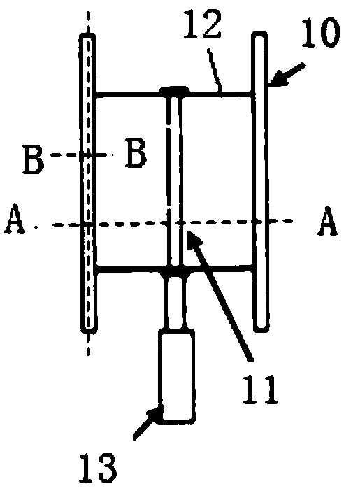
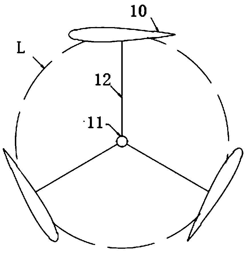
[0020] Such as figure 2 , 3, a H-type vertical axis wind turbine with coaxial jet blades, including jet blades 10, shaft 11, connecting rod 12. A plurality of coaxial jet blades 10 are respectively connected to a rotating shaft 11 through a connecting rod 12 , and the rotating shaft 11 is connected to a generator 13 . A plurality of coaxial jet blades 10 move along the rotation track L, and drive the generator 13 to rotate and generate electricity through the rotating shaft 11 .

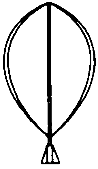
[0021] Such as Figure 4 to Figure 6 As shown, a high-pressure air cavity 1 is set up near the leading edge inside the coaxial jet blade 10, and a low-pressure air cavity 2 is set up near the trailing edge, and the airfoil surface of the coaxial jet blade 10 is located on both sides of the airfoil surface at a distance of 3% of the chord length from the leading edge. The f...


PUM


Abstract

The invention relates to an H-type vertical axis wind turbine with coaxial jet flow blades. A high-pressure air cavity is formed in the position, close to the leading edges, of the interiors of the coaxial jet flow blades, and a low-pressure air cavity is formed in the position, close to the trailing edges, of the interiors of the coaxial jet flow blades. Air jet ports are separately formed in theposition, 3% chord length from the leading edges, of the two sides of the wing section surfaces of the coaxial jet flow blades, air suction ports are separately formed in the position, 80% chord length from the leading edges, of the two sides of the wing section surfaces of the coaxial jet flow blades, and the two air jet ports are correspondingly connected with the high-pressure air cavity through air jet pipelines of the air jet ports. The high-pressure air cavity is connected with a high-pressure air pump which is mounted at the lower ends of the blades, the two air suction ports are correspondingly connected with the low-pressure air cavity through air suction pipelines of the air suction ports, the low-pressure air cavity is connected with a vacuum pump which is mounted at the lowerends of the blades, and electromagnetic valves are correspondingly mounted on the air jet pipelines and the air suction pipelines. According to the H-type vertical axis wind turbine with the coaxial jet flow blades, it is ensured that jet flow moves for a longer distance close to the wing section surfaces of the blades, flow separation can be effectively restrained in a relatively large attack angle range, and thus the acting performance of the blades of the wind turbine is obviously improved.

Description

technical field [0001] The invention relates to an H-type vertical-axis wind power machine, in particular to a blade of an H-type vertical-axis wind power machine. Background technique [0002] The current wind turbine generators can be divided into two types: horizontal axis type and vertical axis type. The output power of horizontal axis wind turbines is relatively high, and the blade diameter is generally about 100 meters, so the required floor space is relatively large, so it is suitable for application in wind speed Higher, wider areas. Compared with the horizontal axis wind turbine, the vertical axis wind turbine does not need to consider the yaw and wind, so the structure is relatively simple, and its generator can be installed on the ground, so it is easy to install and maintain. In addition, the vertical axis wind turbine has low speed and low noise, which is more suitable for use in cities with relatively dense spaces. [0003] Due to the different working princi...

Claims


Application Information

Patent Timeline
IPC IPC(8): F03D3/06
CPCF03D3/005F03D3/062Y02E10/74
Inventor 孙晓晶许应桥苏子昂
Owner UNIV OF SHANGHAI FOR SCI & TECH
Features
  • Generate Ideas
  • Intellectual Property
  • Life Sciences
  • Materials
  • Tech Scout
  • Unparalleled Data Quality
  • Higher Quality Content
  • 60% Fewer Hallucinations
Learn More