High-gain slot array antenna and mobile communication device
A slot array antenna, high-gain technology, applied in slot antennas, antennas, antenna coupling and other directions, can solve the problems of high-order mode out-of-band interference, affect in-band characteristics, reduce the overall performance of the antenna, etc. Plane integration, good performance effect
- Summary
- Abstract
- Description
- Claims
- Application Information
AI Technical Summary
Problems solved by technology
Method used
Image

Examples
Embodiment 1
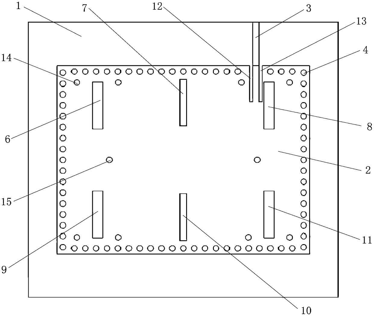
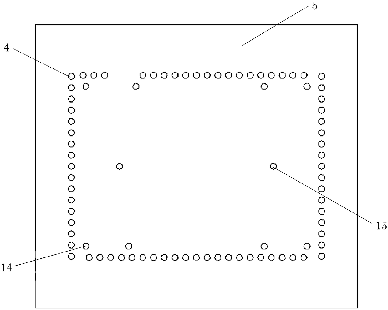
[0037] Such as figure 1 with figure 2 As shown, the present embodiment provides a high-gain slot array antenna, the slot array antenna is a substrate integrated waveguide (SIW) slot array antenna, which can be applied to mobile communication equipment, and it includes a dielectric substrate 1, a patch 2, The microstrip feeder 3 and several first through holes 4, the patch 2 and the microstrip feeder 3 are arranged on the upper surface (front) of the dielectric substrate 1, and the lower surface (back) of the dielectric substrate 1 is the floor 5, that is, the floor 5 covers The entire lower surface of the dielectric substrate 1 .
[0038] The cross-sectional shape of the dielectric substrate 1 is rectangular, its thickness is 0.8 mm, its dielectric constant is 2.55, and its dielectric loss angle is 0.0029. Since there is only one layer of dielectric substrate 1, it is easy to planar integration, simple and cheap, and has good performance.
[0039] Seen from the upper surfac...
Embodiment 2
[0051] The main feature of this embodiment is: the thickness of the dielectric substrate 1 is 0.6 mm. All the other are with embodiment 1.
Embodiment 3
[0053] The main feature of this embodiment is: the thickness of the dielectric substrate 1 is 1 mm. All the other are with embodiment 1.
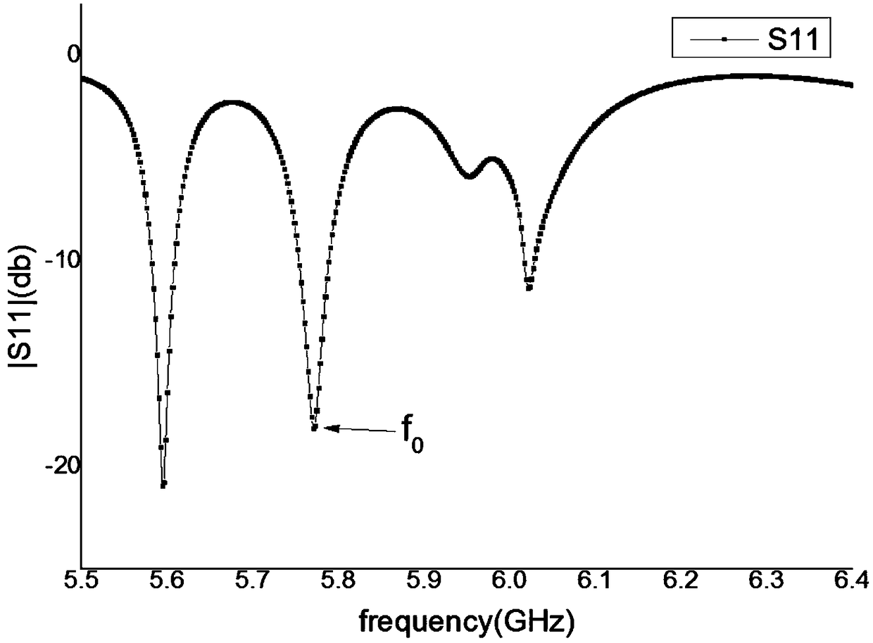
[0054] In summary, the dielectric substrate of the slot array antenna of the present invention is provided with a patch, and six radiation slots are opened on the patch, and the six radiation slots form a six-slot array, which is more effective than a double-slot or four-slot array antenna. Higher gain, without having to achieve the same gain effect by forming an array of multiple antenna elements, thus simplifying the array structure, and because of the use of a layer of dielectric substrate, it is easy to planar integration, simple and cheap process, and good performance; in addition, this The invented slot array antenna divides the six radiation slots into two rows, and the two rows have three radiation slots. The radiation slots on both sides of each row of radiation slots are loaded with a total of eight through holes, which can suppre...
PUM
| Property | Measurement | Unit |
|---|---|---|
| Thickness | aaaaa | aaaaa |
| Thickness | aaaaa | aaaaa |
| Impedance | aaaaa | aaaaa |
Abstract
Description
Claims
Application Information
 - Generate Ideas
- Intellectual Property
- Life Sciences
- Materials
- Tech Scout
- Unparalleled Data Quality
- Higher Quality Content
- 60% Fewer Hallucinations
Browse by: Latest US Patents, China's latest patents, Technical Efficacy Thesaurus, Application Domain, Technology Topic, Popular Technical Reports.
© 2025 PatSnap. All rights reserved.Legal|Privacy policy|Modern Slavery Act Transparency Statement|Sitemap|About US| Contact US: help@patsnap.com