
Stranding machine for wire harness manufacturing

A wire harness and wire clamping technology, which is applied in the direction of line/collector parts, electrical components, connections, etc., can solve the problems of inability to adjust the length of the wire harness, the need for manual twisting of the wires, and poor twisting of the wire harness to achieve good cutting effect , Avoid manual cutting, good clamping effect

Active Publication Date: 2019-07-23
柳州诚飞汽车零部件有限公司
View PDF7 Cites 0 Cited by
  • Summary
  • Abstract
  • Description
  • Claims
  • Application Information

AI Technical Summary

Problems solved by technology

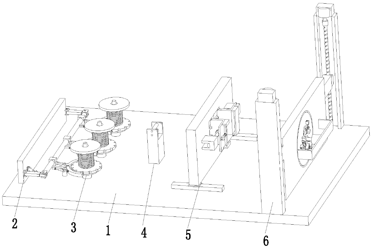
[0004] In order to solve the above problems, the present invention provides a twisting machine for wire harness manufacturing, which can solve the problem that the wires need to be manually twisted during the manufacturing process of the existing wire harness, the manual operation efficiency is low, the degree of twisting of the wire harness is poor, and the wire harness is easy to twist. The phenomenon of unraveling occurs, and the existing device cannot tighten the wires during the twisting process of the wire harness. The existing device can only process a wire harness of one length, and the length of the wire harness cannot be adjusted. The adaptability effect is poor, and the wire harness During the cutting process, the incision is not smooth, which affects the subsequent processing, complex operation, high labor intensity, low production efficiency and other problems. It realizes the function of automatic twisting and cutting of the wire harness, and can automatically twist the wires and clamp the wires. Tight, to avoid loose wires, can adjust the length of the wire harness, strong adaptability, good wire cutting effect, simple operation, good stability, high production efficiency, etc.

Method used


Image

  • Stranding machine for wire harness manufacturing
  • Stranding machine for wire harness manufacturing
  • Stranding machine for wire harness manufacturing

Examples


Embodiment Construction

[0034] In order to make the technical means, creative features, goals and effects achieved by the present invention easy to understand, the present invention will be further described below in conjunction with specific illustrations. It should be noted that, in the case of no conflict, the embodiments in the present application and the features in the embodiments can be combined with each other.

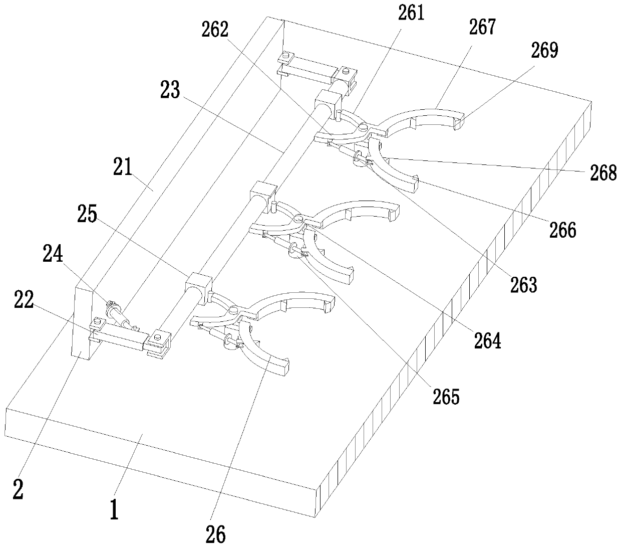
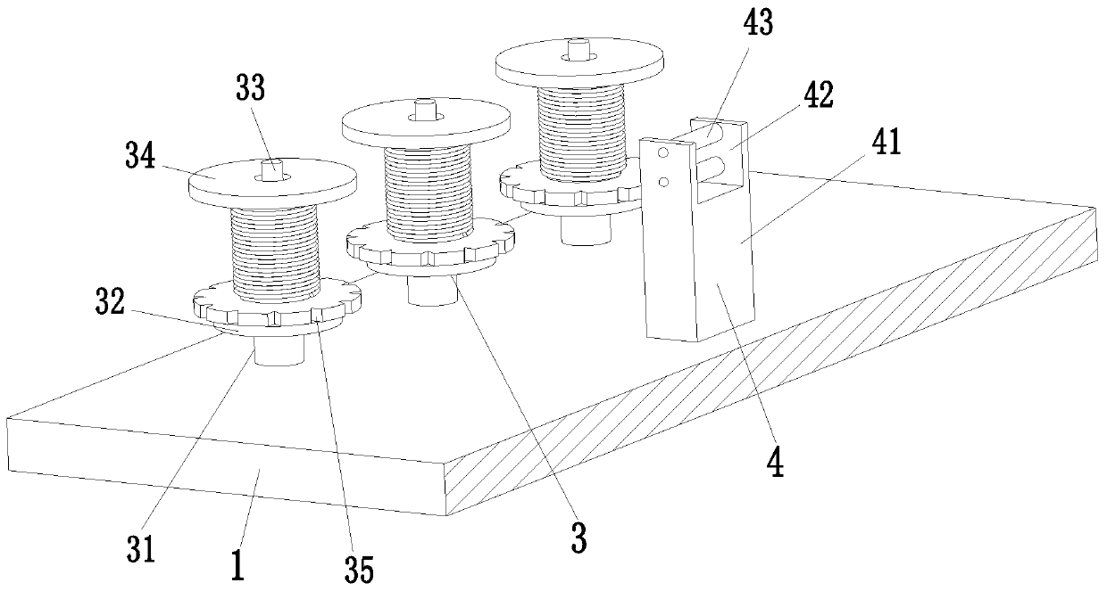
[0035] Such as Figure 1 to Figure 9 As shown, a stranding machine for wire harness manufacturing includes a base plate 1, a clamping device 2, a wire releasing device 3, a wire device 4, a clamping and cutting device 5, and a twisting lifting device 6. A clamp is installed on the left side of the upper end of the base plate 1. Tightening device 2, the right side of the clamping device 2 is provided with a pay-off device 3, the pay-off device 3 is evenly installed on the bottom plate 1 from front to back, and the middle part of the upper end of the base plate 1 is installed with a cl...


PUM


Abstract

A stranding system for manufacturing a wire harness and a method for manufacturing and processing the wire harness are disclosed, the system including a bottom plate, a clamping device, a release device, a conductor device, a wire clamping and cutting device and a stranding lifting device. The clamping device is arranged on the left side of the upper end of the bottom plate, the release device isarranged on the right side of the clamping device, the wire clamping and cutting device is arranged on the middle part of the upper end of the bottom plate, the conductor device is arranged between the wire clamping and cutting device and the release device, and the stranding lifting device is arranged on the right side of the upper end of the bottom plate. The invention can solve the problem thatin the conventional manufacturing process of the wire harness, conductors require manual stranding, the manual efficiency is low, the stranding of wire harness is poor and the wire harness is liableto spread out, and in the stranding process of the existing device, the conductors can-not be tensioned; the existing device can only process the wire harness of one length, cannot adjust the length of wire harness, and the adaptability effect is poor; in the cutting process, the cut of the wire harness is uneven, the operation is complex, the labor intensity is large, the production efficiency islow.

Description

technical field [0001] The invention relates to the field of wire harness manufacturing, in particular to a stranding machine for wire harness manufacturing. Background technique [0002] The wire harness refers to the contact terminal (connector) made of copper punched and crimped with the wire, and the outside is molded with an insulator or a metal shell, etc., and is bundled with a wire harness to form a connected circuit assembly. The wire harness industry chain includes wires, connectors, processing equipment, wire harness manufacturing and downstream application industries. Wire harnesses are widely used and can be used in automobiles, household appliances, computers and communication equipment, and various electronic instruments and meters. [0003] In the process of manufacturing the existing wire harness wire harness, the wires need to be twisted manually, the efficiency of manual operation is low, the degree of twisting of the wire harness is poor, and the wire har...

Claims


Application Information

Patent Timeline
IPC IPC(8): H01R43/28
CPCH01R43/28
Inventor 吴丹
Owner 柳州诚飞汽车零部件有限公司
Learn More