Upper box-type dense cooling device

A cooling device, box-type technology, applied in the direction of workpiece cooling device, workpiece surface treatment equipment, metal rolling, etc., can solve the problems of water resource waste, response delay, etc., to achieve reduced impact, fast response speed, and good cooling uniformity Effect

Active Publication Date: 2018-12-28
YANSHAN UNIV +1
View PDF10 Cites 0 Cited by
  • Summary
  • Abstract
  • Description
  • Claims
  • Application Information

AI Technical Summary

Problems solved by technology

However, there is a lot of water stored in the box-type nozzle cooler for intensive cooling, and the nozzle is located below the cooler. When the nozzle is located at the cooling start an

Method used


Image

  • Upper box-type dense cooling device
  • Upper box-type dense cooling device
  • Upper box-type dense cooling device

Examples


Embodiment 1

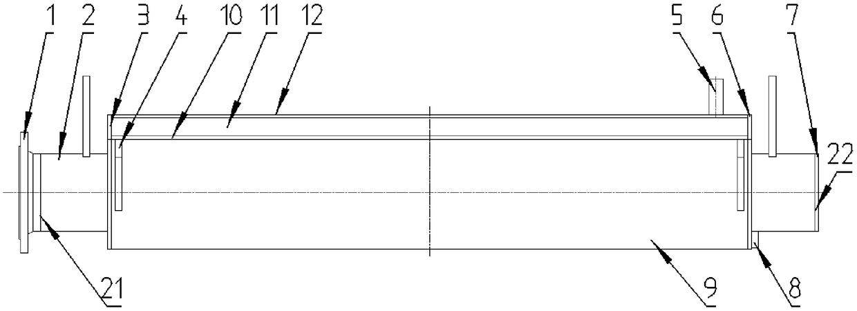
[0028] Such as figure 1 As shown, the top-mounted box-type intensive cooling device for strip steel controlled cooling of the present invention includes a water inlet header 2 and a water spray device main body 9 sleeved on the water inlet header 2 . The second end 21 of the water inlet header 2 is connected with the connecting flange 1 coaxially, and the first end 22 of the water inlet header 2 is fixedly connected with the header end plate 7 to form a part of the water inlet header together; The lower part of the pipe 2 is provided with damping holes 16 uniformly distributed in the circumferential direction to ensure the uniformity of water flow in the length direction of the cooling device; They are respectively fixedly connected with the side plate 3 on the water inlet side and the side plate 6 on the drain side to form the main part of the cooling device; The nozzle installation hole 17 is used to install the dense nozzle 13; the height of the top of the nozzle 13 is hig...

Embodiment 2

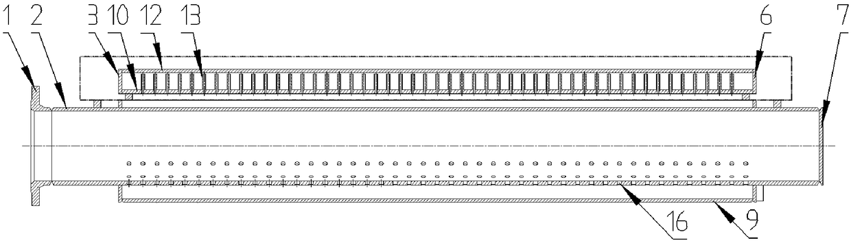
[0036] Such as Figure 6 Shown is another embodiment of the specific embodiment.

[0037]The difference between the second embodiment of the present invention and the first embodiment is that the spray pipe mounting plate 10 connected to both sides on the sprinkler main body 9 is a whole, and the spray pipe mounting plate has a square hole 18, so that The cooling water passes through, and two buffer fixing plates 15 are connected between the nozzle mounting plate 10 and the top plate. The two buffer fixing plates 15, the nozzle mounting plate 10, and the top plate 12 form a cavity to reduce cooling when the cooling device starts and stops. The changing volume of water; the buffer plate 15 is fixedly connected to the buffer plate 14, so that when the cooling water enters the upper intensive cooling part from the main part of the cooling device, the direction of the water flow is changed from vertical upward to horizontal, so as to avoid the impact of the cooling water on the no...


PUM

PropertyMeasurementUnit
Angleaaaaaaaaaa
Diameteraaaaaaaaaa
The inside diameter ofaaaaaaaaaa

Abstract

The invention provides an upper box-type dense cooling device, and relates to a rolled steel production line controlled cooling technology in the field of metal processing. The upper box-type dense cooling device is arranged on the upper portion of a plate strip steel transporting roller way and comprises a dense cooling part, a cooling device main body part and a water inlet collecting pipe part.Cooling water enters a water inlet collecting pipe through a connecting flange, the water inlet collecting pipe is provided with damping holes for flow stabilizing of the cooling water, then the cooling water enters a cooling device main body to reach the dense cooling part on the upper portion, the cooling water is sprayed out from spraying pipes and sprayed to a hot steel plate on the lower portion of the upper box-type dense cooling device, and high-strength uniform cooling is conducted on the surface of a plate strip. The upper box-type dense cooling device has the advantages of small spraying pipe spacing, large number of the spraying pipes, good cooling uniformity, large cooling capacity, good starting and emergency stopping characteristic, easy processing and the like, and can fully meet the process requirements of on-line or offline controlled cooling of the hot-rolled plate strip.

Description

technical field [0001] The invention relates to the controlled cooling technology of a steel rolling production line in the field of metal processing, in particular to an upper box-type intensive cooling device. Background technique [0002] Controlled cooling refers to the on-line controlled cooling of the hot-rolled steel plate, which aims to control the phase transformation structure of the steel plate and improve the mechanical properties of the steel plate. The controlled cooling of the steel plate after hot rolling can greatly increase the strength and toughness of the steel plate, and has a direct contribution to energy saving. [0003] At present, for the control cooling device of medium and heavy plate and hot-rolled strip steel production line, U-shaped tube and lower box-type dense cooling nozzle cooler are mainly used. U-shaped tubes have the advantage of quick response when starting and stopping, and are widely used in laminar flow cooling. However, the arrange...

Claims


Application Information

Patent Timeline
IPC IPC(8): B21B45/02
CPCB21B45/0233Y02P70/10
Inventor 黄华贵赵日东高林张尚斌杨瑞宇燕猛季策钟方君
Owner YANSHAN UNIV
Why Eureka
Try Eureka