
Device and method for machining flywheel assembly

A processing device and processing method technology, which is applied in the direction of manufacturing tools and other manufacturing equipment/tools, etc., can solve the problems of high production cost, low manufacturing precision of flywheel discs, heavy manual load, etc., so as to reduce the defective rate of product processing and reduce labor costs. Labor intensity, the number of workers, and the effect of reducing monthly waste loss

Active Publication Date: 2018-12-28
十堰东风飞斯特机械制造有限公司
View PDF6 Cites 2 Cited by
  • Summary
  • Abstract
  • Description
  • Claims
  • Application Information

AI Technical Summary

Problems solved by technology

[0004] The purpose of the present invention is to solve the shortcomings in the prior art and provide a commercial vehicle that solves the technical problems of low manufacturing precision, low production efficiency, long process flow, heavy manual load and high production cost of the flywheel disc with rectangular signal tooth structure. Production process of flywheel assembly for engine

Method used


Image

  • Device and method for machining flywheel assembly
  • Device and method for machining flywheel assembly
  • Device and method for machining flywheel assembly

Examples


Embodiment Construction

[0026] The following will clearly and completely describe the technical solutions in the embodiments of the present invention with reference to the accompanying drawings in the embodiments of the present invention. Obviously, the described embodiments are only some of the embodiments of the present invention, not all of them.

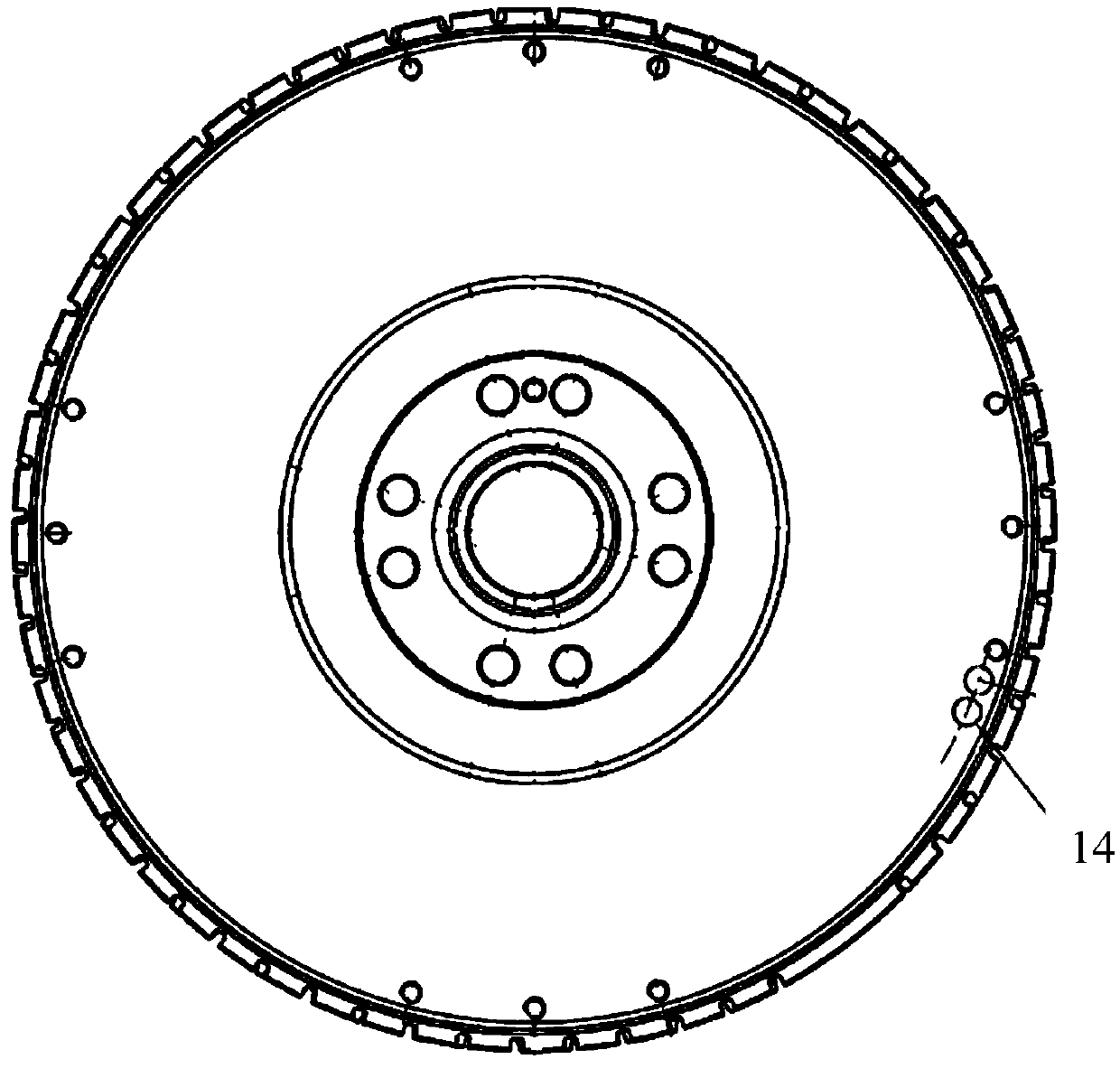
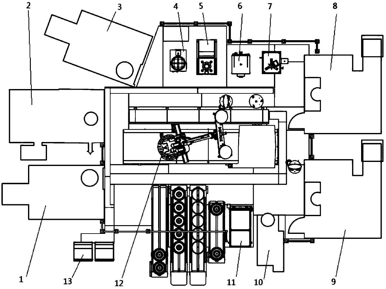
[0027] refer to image 3 , the processing device of the flywheel assembly, including the first vertical lathe 1, the horizontal lathe 2, the second vertical lathe 3, the ring gear heating device 4, the press 5, the cleaning table 6, the online detection device 7, the first vertical lathe 8 , The second vertical plus 9, dynamic balancing equipment 10, infrared scanning and laser marking machine 11, robot 12, automation system 13, dynamic balancing hole 14, ring gear 15, flywheel 16.

[0028] Processing method of flywheel assembly:

[0029] After the system is started, firstly the first vertical lathe 1 opens the protective door after finishing the proce...


PUM


Abstract

The invention discloses a device and a method for machining a flywheel assembly. The whole machining processes are sequentially as follows: a first vertical lathe is used for machining the front surface of a flywheel; a horizontal machining unit is used for performing flywheel signal gear machining; a gear ring heating device is used for heating a gear ring; a press machine is used for carrying out gear ring and flywheel pressing and sleeving; a second vertical lathe is used for machining the working face of the flywheel; a cleaning workbench is used for cleaning the flywheel; an online detection device is used for carrying out online detection on the flywheel; an infrared scanning unit is used for carrying out infrared scanning and positioning on the flywheel; a first vertical machining unit is used for carrying out flywheel hole position machining; a second vertical machining unit is used for carrying out flywheel installation hole machining; a laser marking machine is used for carrying out laser printing of an ignition mark; and dynamic balance equipment is used for carrying out dynamic balancing of the flywheel. According to the device and the method, due to the adoption of a roundabout layout of automatic operation of manipulators, the labor intensity of workers and the number of the workers are greatly reduced, the fact the process capabilities of important sizes of products are all 1.67 or above is ensured, the reject ratio of product machining is remarkably reduced, and the monthly waste loss is reduced by 50% or above.

Description

technical field [0001] The invention relates to the technical field of automobile manufacturing, in particular to a processing device and method for a flywheel assembly for a commercial vehicle engine. Background technique [0002] The flywheel is the key starting part of the automobile engine. It is generally a thick disc. Its size, weight and balance performance seriously affect the performance of the engine. Therefore, it has both certain dimensional accuracy requirements and certain dynamic requirements. unbalanced volume requirements. With the improvement of the engine performance requirements of the automobile, the requirements for the schedule and dynamic balance of the flywheel also increase accordingly. [0003] The traditional flywheel assembly consists of a flywheel disc and a flywheel ring gear. The flywheel ring gear is shrunk onto the flywheel disc to form a flywheel ring gear assembly. There are rectangular signal teeth (or peripheral drilling) on ​​the flywh...

Claims


Application Information

Patent Timeline
Patent Type & Authority Applications(China)
IPC IPC(8): B23P23/04B23P23/06B23P15/14
CPCB23P15/14B23P23/04B23P23/06
Inventor 张波
Owner 十堰东风飞斯特机械制造有限公司
Learn More