
A wear-resistant screw of a twin-screw extruder and its processing technology

A twin-screw extruder and machining technology, applied in metal material coating process, coating, melt spraying, etc., can solve the problems of screw failure, screw component wear, high cost of screw, etc., to achieve tight combination and fixation , Improve the wear resistance, and the effect of low processing difficulty

Active Publication Date: 2021-03-19
BEIJING TECHNOLOGY AND BUSINESS UNIVERSITY +1
View PDF6 Cites 0 Cited by
  • Summary
  • Abstract
  • Description
  • Claims
  • Application Information

AI Technical Summary

Problems solved by technology

During the material extrusion process, the material will friction and wear with the surface of the screw, which will cause the gap between the screw and the barrel to increase, increase the leakage flow of the extruded material when it advances, and affect the normal operation of the twin-screw extruder. Severe wear on the surface of the screw element makes the screw unusable
[0003] Currently commonly used screw alloy materials include 45 steel, 40Cr steel, 38CrMoAlA, etc., and nitriding treatment is used to improve its wear resistance, but in order to improve the extrusion performance of the material, it is often necessary to add a lot of fillers, such as calcium carbonate, glass fiber And talcum powder, due to its high hardness will lead to rapid wear of the screw, and some screws will fail in about 6 months, and the cost of replacing the screw is very high, using cemented carbide coating containing Cr, W, Co, B and other elements Spraying and surfacing repair treatment can make the screw reuse for extrusion process
However, field experience shows that the service life of the repaired screw needs to be further improved. Once new wear occurs in other parts, the screw will need to be replaced again, which will affect the normal production

Method used


Image

  • A wear-resistant screw of a twin-screw extruder and its processing technology
  • A wear-resistant screw of a twin-screw extruder and its processing technology

Examples


Embodiment Construction

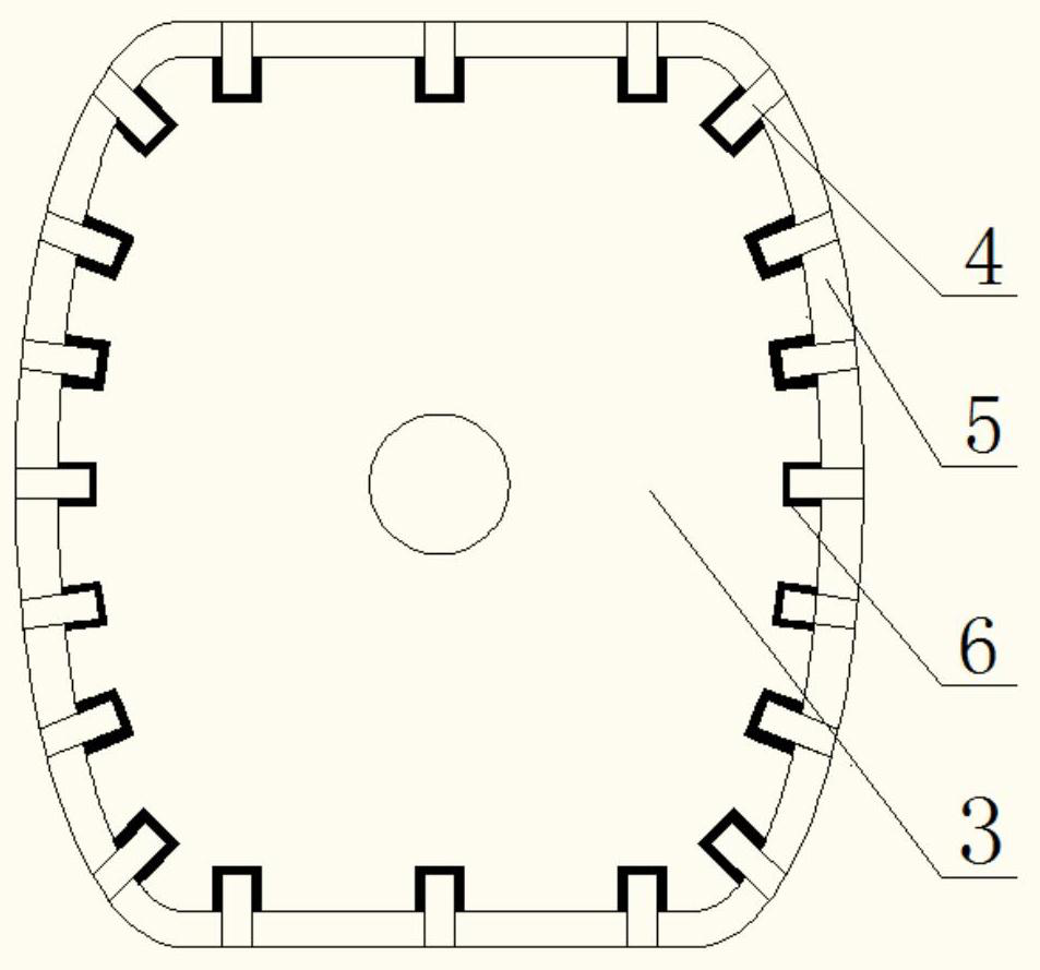
[0026] see figure 1 and figure 2 According to the wear-resistant screw of a twin-screw extruder provided by the present invention, the main technical scheme adopted is: the kneading block 2 of the screw 1 includes a steel substrate 3, a silicon nitride ceramic rod 4 and an alloy coating 5. Dimples 6 are evenly distributed on the outer surface of the steel base 3 parallel to the axial direction of the screw 1, half of the silicon nitride ceramic rod 4 in the length direction is in the dimples 6, so The other half of the silicon nitride ceramic rod 4 in the length direction is exposed outside the surface of the substrate 3, the alloy coating 5 covers the entire surface of the substrate 3, and the top end of the silicon nitride ceramic rod 4 is exposed Outside the alloy coating 5 . The wear resistance of the kneading block can be significantly improved by introducing silicon nitride ceramic components with extremely high hardness on the surface of the steel substrate 3, especi...


PUM

PropertyMeasurementUnit
diameteraaaaaaaaaa
surface roughnessaaaaaaaaaa

Abstract

With increase of amount of filler in extruded materials, abrasion to a screw rod of a double-screw extruder is increasingly serious, and as a kneading block is a main component for shearing and extruding materials, it is very urgent to solve the problem about abrasion. The invention provides an abrasion-resistance screw rod of a double-screw extruder. The kneading block of the screw rod comprisesa steel base, silicon nitride ceramic bars and an alloy coating, concave pits are evenly distributed in the outer surface, parallel to the axis direction of the screw rod, of the steel base; the halfportions of the silicon nitride ceramic bars in the length direction are located in the concave pits, the other half portions of the silicon nitride ceramic bars in the length direction are exposed outside the surface of the steel bar, the alloy coating completely covers the surface of the steel base, and the top ends of the silicon nitride ceramic bars are exposed outside the alloy coating. According to the abrasion-resistance screw rod, the problem about abrasion to the screw rod of the double-screw extruder can be effectively solved.

Description

technical field [0001] The invention relates to twin-screw extruder equipment, and more specifically relates to a wear-resistant screw of a twin-screw extruder and a processing technology thereof. Background technique [0002] The screw is an important part in the twin-screw extruder, and wear is one of the main reasons for its failure. During the material extrusion process, the material will friction and wear with the surface of the screw, which will cause the gap between the screw and the barrel to increase, increase the leakage flow of the extruded material when it advances, and affect the normal operation of the twin-screw extruder. Severe wear on the surface of the screw element makes the screw unusable. [0003] Currently commonly used screw alloy materials include 45 steel, 40Cr steel, 38CrMoAlA, etc., and nitriding treatment is used to improve its wear resistance, but in order to improve the extrusion performance of the material, it is often necessary to add a lot o...

Claims


Application Information

Patent Timeline
Patent Type & Authority Patents(China)
IPC IPC(8): B29C48/57B29C48/25C23C4/06C23C4/123
CPCC23C4/06C23C4/123
Inventor 黄志刚翁云宣田斌张丽梅应高波宋宇王少峰
Owner BEIJING TECHNOLOGY AND BUSINESS UNIVERSITY
Learn More