A high efficient solar energy cooling device for shielding a vehicle body

A cooling device, solar energy technology, applied in circuit devices, battery circuit devices, electric vehicles, etc., can solve the problems of shortened service life, accelerated aging of components, damage to leather accessories, etc., and achieves compact device structure, high automation level, and cooling. good effect

Pending Publication Date: 2018-12-28
SHANDONG UNIV OF SCI & TECH
10 Cites 0 Cited by

AI-Extracted Technical Summary

Problems solved by technology

3. The materials such as car interior accessories are mainly leather, fabric, composite materials, etc. After being exposed to high temperature, it will accelerate the release of various harmful substances inside, such as formaldehyde, benzene, etc., posing a threat to human healt...

Method used

Further, described sun visor 2 is provided with two in total and is positioned at the top and the bottom of shell 1 respectively, and the upper surface of the sun visor 2 of shell 1 top is provided with film solar panel 2c and lower surface is provided with The transmission rack 2b, the upper surface of the sun visor 2 at the bottom of the housing 1 is provided with a thin-film solar cell panel 2c and the upper surface is provided with a transmission rack 2b, so that the device has a larger shading area and can better utilize the sun. Energy;...

Abstract

The invention discloses a high-efficient solar energy cooling device for shielding a vehicle body, which comprises an outer shell, a sunshade plate, a convex lens group, a solar cell panel, a coolinglayer, a fan layer, a control box and a support pedestal, wherein, the cooling device comprises a housing, a sunshade plate, a convex lens group, a solar cell panel, a cooling layer, a fan layer and acontrol box. The inside of the shell is sequentially provided with a sunshade from the top to the bottom, A convex lens group, a solar cell panel, a cooling layer, a fan layer and a sun visor are arranged at the center of the lower surface of the fan layer; a control box is arranged inside the control box; a battery, a temperature sensor and a core processor are arranged; four corners of the outer periphery of the shell are respectively provided with a supporting foot seat; and the device is installed on the top of the vehicle. The device can not only shield the car body from sunlight, but also use solar energy to convert the solar energy into electric energy to drive the fan and the cooling sheet to cool the car body, so as to avoid a series of problems caused by the high-temperature exposure of the private car; Solar energy is used as the energy source of the device, which is safe, economical and environmentally friendly. The device is compact in structure, convenient in installation and high in automation level, which is worth popularizing and using in a wide range.

Application Domain

Air-treating devicesBatteries circuit arrangements +4

Technology Topic

Environmentally friendlyElectric energy +8

Image

  • A high efficient solar energy cooling device for shielding a vehicle body
  • A high efficient solar energy cooling device for shielding a vehicle body
  • A high efficient solar energy cooling device for shielding a vehicle body

Examples

  • Experimental program(1)

Example Embodiment

[0021] The technical solutions in the embodiments of the present invention will be clearly and completely described below in conjunction with the accompanying drawings in the embodiments of the present invention. Obviously, the described embodiments are only a part of the embodiments of the present invention, not all the embodiments. Based on the embodiments of the present invention, all other embodiments obtained by those of ordinary skill in the art without creative work shall fall within the protection scope of the present invention.
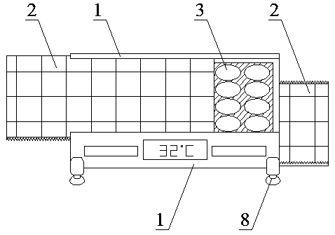
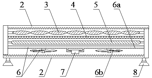
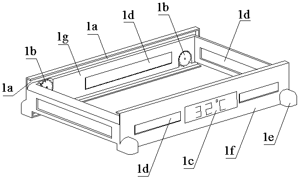
[0022] See Figure 1 to Figure 8 , This specific embodiment adopts the following technical solutions: a cooling device that shields the car body and uses solar energy efficiently, including a housing 1, a sun visor 2, a convex lens group 3, a solar panel 4, a cooling layer 5, a fan layer 6, and a control box 7. And supporting feet 8; the inside of the housing 1 is provided with sun visor 2, convex lens group 3, solar panel 4, cooling layer 5, fan layer 6 and sun visor 2, from top to bottom. The center of the lower surface of fan layer 6 The control box 7 is provided with a battery 7a, a temperature sensor 7b, and a core processor 7c inside the control box 7, and the four corners of the outer periphery of the housing 1 are respectively provided with support feet 8, and the device is installed on the top of the vehicle.
[0023] Furthermore, the refrigeration layer 5 adopts TEC1-12706 type semiconductor refrigeration sheet, which has no moving parts, high reliability, and relatively low cost.
[0024] The casing 1 is composed of a casing body 1f, a driving gear 1b, a display screen 1c and a connecting ear 1e. The top and bottom of the casing body 1f are respectively provided with two-sided symmetrical sun visor slides 1a, and the sides of the casing body 1f are provided with Ventilation holes 1d, the inner surface of the side vent 1d of the housing body 1f is provided with a reflective film 1g, the outer four corners of the housing body 1f are respectively provided with connecting ears 1e, and the middle of the outer surface of the housing body 1f is provided with a display screen 1c. Drive gears 1b are respectively provided at both ends of the inner side of the body 1f;
[0025] Furthermore, the above-mentioned driving gear 1b is driven by an ultra-thin motor. The ultra-thin motor adopts a 35SHD0303 motor, which is compact in structure and takes up less space and is low in price.
[0026] The sun visor 2 is composed of a sun visor body 2a, a transmission rack 2b, and a thin-film solar panel 2c. The surface of the sun visor body 2a is provided with two symmetrically distributed transmission racks 2b, and the transmission racks 2b are connected with each other. The driving gears 1b mesh with each other, and a thin-film solar cell panel 2c is provided on the surface of the sun visor body 2a.
[0027] Furthermore, there are two sun visors 2 in total and they are located at the top and bottom of the housing 1. The sun visor 2 on the top of the housing 1 has a thin-film solar panel 2c on its upper surface and a transmission rack on its lower surface. 2b. The upper surface of the sun visor 2 at the bottom of the housing 1 is provided with a thin-film solar panel 2c and a transmission rack 2b is provided on the upper surface, so that the device has a larger shading area and better use of solar energy after unfolding; A sliding connection is adopted between the board 2 and the sun visor slideway 1 a of the housing 1 to facilitate the automatic expansion and contraction of the sun visor 2.
[0028] The fan layer 6 is composed of a suspension plate 6a and a fan 6b, and the lower surface of the suspension plate 6a is provided with four symmetrically distributed fans 6b.
[0029] The supporting foot 8 is composed of two parts: a stud 8a and a suction cup 8b.
[0030] The solar cell panel 4 and the thin-film solar cell panel 2c are respectively electrically connected to the battery connection 7a through wires. A voltage stabilizing module is provided between the solar cell panel 4, the thin-film solar cell panel 2c and the battery 7a, the display screen 1c, the battery The connection 7a, the temperature sensor 7b and the fan 6b are respectively electrically connected to the core processor 7c through wires, and the ultra-thin motor driving the driving gear 1b is electrically connected to the core processor 7c.
[0031] Furthermore, the core processor 7c adopts STM32 type single-chip microcomputer.
[0032] In another preferred embodiment of the invention, the threaded connection is adopted between the stud 8a of the support foot 8 and the connecting ear 1e of the housing 1, so as to adjust the height of the device arbitrarily according to needs, and better adapt to different car models. .
[0033] The working principle of the present invention: First, the temperature sensor 7b transmits the detected temperature signal to the core processor 7c, and the temperature is preset with a threshold, for example, when the temperature is greater than 35°C, the core processor 7c controls other mechanisms to start working; , The drive gear 1b rotates, and the sun visor 2 is driven to expand to both sides through the transmission rack 2b. The thin-film solar panel 2c converts light energy into electric energy and stores it in the battery connection 7a. The light in the middle part of the device shines through the convex lens group 3 The battery panel 4 also converts light energy into electrical energy and stores it in the battery connection 7a. The convex lens group 3 can play a role in concentrating light to make solar energy use more efficient; at the same time, the fan 6b and the cooling layer 5 work to accelerate air flow and cooling Reduce the temperature, so as to achieve the purpose of cooling. When the temperature is lower than 35°C, the core processor 7c controls the driving gear 1b to rotate in the reverse direction, and drives the sun visor 2 to shrink inward through the transmission rack 2b, and the device is used.
[0034] For those skilled in the art, it is obvious that the present invention is not limited to the details of the foregoing exemplary embodiments, and the present invention can be implemented in other specific forms without departing from the spirit or basic characteristics of the present invention. Therefore, from any point of view, the embodiments should be regarded as exemplary and non-limiting. The scope of the present invention is defined by the appended claims rather than the above description, and therefore it is intended to fall within the claims. All changes within the meaning and scope of equivalent elements of are included in the present invention. Any reference signs in the claims should not be regarded as limiting the claims involved.

PUM

no PUM

Description & Claims & Application Information

We can also present the details of the Description, Claims and Application information to help users get a comprehensive understanding of the technical details of the patent, such as background art, summary of invention, brief description of drawings, description of embodiments, and other original content. On the other hand, users can also determine the specific scope of protection of the technology through the list of claims; as well as understand the changes in the life cycle of the technology with the presentation of the patent timeline. Login to view more.

Similar technology patents

Control panel cabinet placed in open air

InactiveCN104505750AGood rainproof performanceGood cooling effect
Owner:重庆新世纪电气有限公司

Thermal-shrinkage tube expanding mould

ActiveCN101028734Agood cooling effectStable expansion
Owner:CHANGYUAN GRP

Roll cooling method for rolling of composite metal and special cooling device

InactiveCN103599942AImprove the composite effect of metal materialsgood cooling effect
Owner:YINBANG CLAD MATERIAL

Classification and recommendation of technical efficacy words

  • good cooling effect
  • The device is compact

Runner type online degassing device

InactiveCN101781712AThe device is compactLittle space required
Owner:江西金达通新材料科技有限公司

Thermal desorption device

ActiveCN104458970AThe device is compactwell fixed
Owner:DALIAN INST OF CHEM PHYSICS CHINESE ACAD OF SCI
Why Eureka
Try Eureka