Multidirectional Fluid Drive System Based on Pressure Control and Its Application

A technology of fluid flow direction and pressure, applied in the field of microfluidics, can solve problems such as incompatibility, and achieve the effect of improving efficiency and improving the degree of automation

Active Publication Date: 2021-08-24
TSINGHUA UNIV +1
View PDF0 Cites 0 Cited by
  • Summary
  • Abstract
  • Description
  • Claims
  • Application Information

AI Technical Summary

Problems solved by technology

Although the pressure can change the flow state of the fluid in real time, the traditional method is to change the output pressure by changing the pressure of the pressure source. This process still takes a few seconds, and it is still not suitable for microsphere cleaning, which requires fast fluid flow. In case of reversing

Method used


Image

  • Multidirectional Fluid Drive System Based on Pressure Control and Its Application
  • Multidirectional Fluid Drive System Based on Pressure Control and Its Application
  • Multidirectional Fluid Drive System Based on Pressure Control and Its Application

Examples


Embodiment 1

[0022] Embodiment 1: A two-way fluid drive system

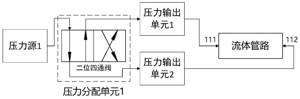
[0023] figure 1 The left half of the figure is a schematic structural diagram of a two-way fluid drive system, which includes: a pressure source 1, a pressure distribution unit 1 and two pressure output units 1-2. The pressure in the pressure source 1 is higher than the atmospheric pressure; the pressure distribution unit 1 includes a two-position four-way valve, one of its air inlets is connected to the pressure source 1, the other air inlet is connected to the atmosphere, and the two air outlets are respectively connected to Two pressure output units 1-2; two pressure output units 1-2 are respectively connected to figure 1 The fluid pipe ends 111 and 112 of the right half.

[0024] When the two-position four-way valve is in the normal position, the pressure of the pressure source 1 is connected to the 111 end of the fluid pipeline by the pressure distribution unit, and the atmospheric pressure is connected to the 112 end ...

Embodiment 2

[0026] Embodiment 2: A two-way fluid drive system

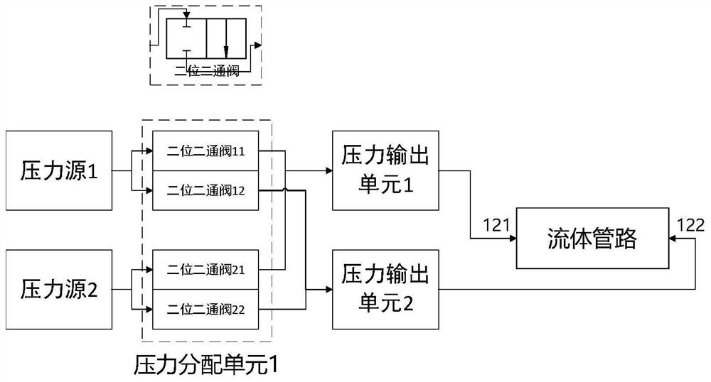
[0027] figure 2 The left half of the figure is a schematic structural diagram of a two-way fluid drive system, which includes: two pressure sources 1-2, one pressure distribution unit 1 and two pressure output units 1-2. The pressure in the pressure source 1 is higher than the pressure in the pressure source 2; the pressure distribution unit 1 includes four two-position two-way valves (normal position: close the flow path, working position: connect the flow path), and the numbers are respectively ij= 11, 12, 21, 22, the number ij mentioned indicates that the inlet port of the two-position two-way valve is connected to the pressure source i, and the gas outlet is connected to the pressure output unit j; the two pressure output units are respectively connected to figure 1 The two ends 121 and 122 of the fluid conduit of the right half.

[0028] When the two-position two-way valves 11 and 22 are in the working position and th...

Embodiment 3

[0033] Embodiment 3: A dual-channel bidirectional fluid drive system

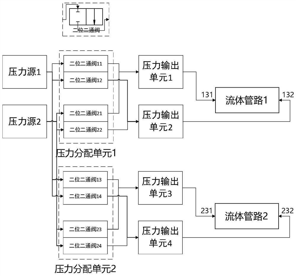
[0034] image 3 The left half of the figure is a schematic structural diagram of a dual-channel bidirectional fluid drive system, which includes two pressure sources, two pressure distribution units and two pressure output units, respectively driving the two fluid pipelines 1-2 in the right half of fluid.

[0035] Similar to Embodiment 2, each pressure distribution unit can independently control the movement direction and movement / stationary state of the fluid in each fluid pipeline: the pressure distribution unit 1 can control the fluid pipeline 1 through the interfaces 131-132 at both ends of the fluid pipeline The pressure at both ends (the pressure of pressure source 1 or pressure source 2), so as to control the movement direction and movement / rest state of the fluid; the pressure distribution unit 2 can control the pressure at both ends of the fluid pipeline 2 through the interfaces 231-232 at both en...


PUM


Abstract

The invention provides a multi-directional fluid drive system based on pressure control and its application. The system includes at least one pressure source, at least one pressure distribution unit and at least two pressure output units. Using the system, without changing the pressure of the pressure source, the connection relationship between the pressure source and the pressure output unit can be changed through the pressure distribution unit, so as to realize the multi-directional driving and driving direction of the microfluidic, and the rapid movement / stationary Switch to increase the automation of biochemical applications such as bead washing.

Description

technical field [0001] The invention relates to the field of microfluidic technology, in particular to a multidirectional fluid drive system based on pressure control and its application. Background technique [0002] Microfluidic technology is a biochemical analysis technology that has developed rapidly in recent years. It has potential advantages such as high throughput, high detection sensitivity, low cost, and easy automation, making it widely used in biochemical detection, especially in the field of biomedicine. Application prospects. Microfluidic technology requires fluid drive technology with adjustable flow and flow direction. Taking the cleaning of microspheres in microfluidic chips as an example, in order to achieve efficient cleaning in a short time, it is also necessary to drive microfluidics to drive the microspheres to reciprocate in a limited space. [0003] Currently, there are mainly two approaches to achieve fluid-driven commutation. One method utilizes ...

Claims


Application Information

Patent Timeline
Patent Type & Authority Patents(China)
IPC IPC(8): C12M1/00C12Q1/6844C12Q1/6869G01N33/68
CPCC12M23/16C12Q1/6844C12Q1/6869G01N33/68C12Q2563/159
Inventor 苏世圣朱修锐郭永山口悠介刘君元王勇斗
Owner TSINGHUA UNIV
Why Eureka
Try Eureka