Movable stirring-type coprecipitation device for rare earth
A precipitation device and stirring type technology, applied in the direction of improving process efficiency, can solve problems such as affecting product quality, inability to adjust, and uneven mixing reaction of rare earth mixed material and liquid, and achieve the effect of good stirring effect and wide stirring range.
- Summary
- Abstract
- Description
- Claims
- Application Information
AI Technical Summary
Problems solved by technology
Method used
Image

Examples
Embodiment 1
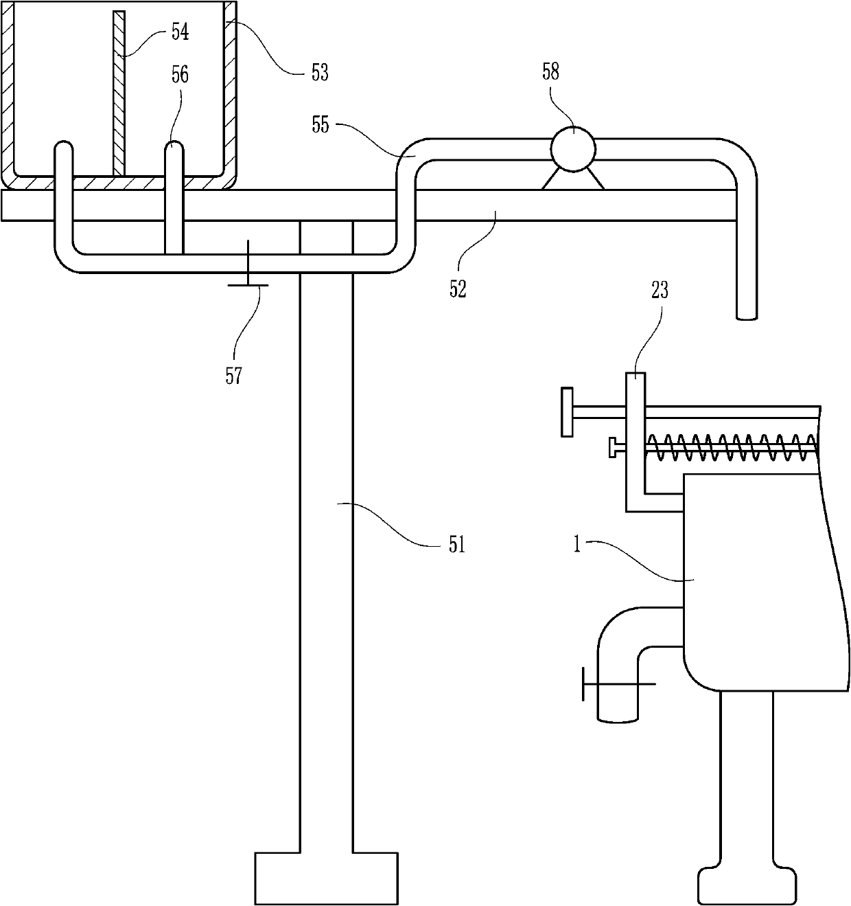
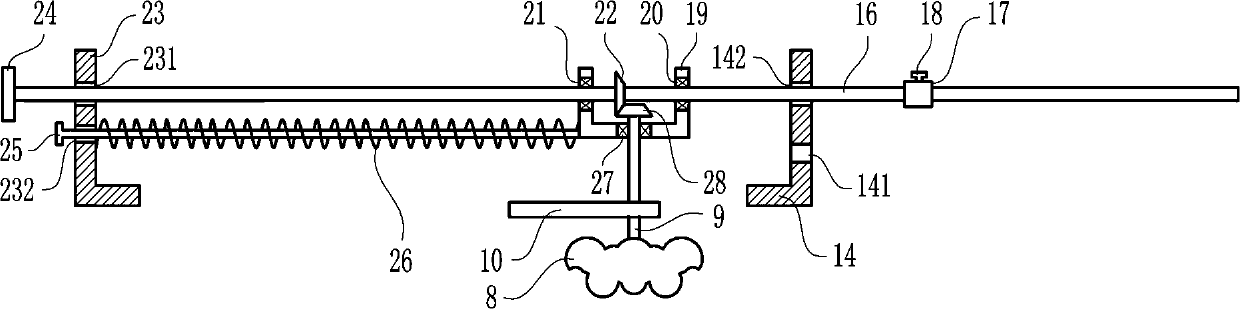
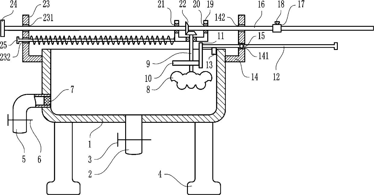
[0025] A movable stirring type co-precipitation device for rare earth, such as Figure 1-6 As shown, it includes a sedimentation tank 1, a discharge pipe 2, a first valve 3, a leg 4, a discharge pipe 5, a second valve 6, a filter screen 7, a large stirring plate 8, a first connecting shaft 9, and a small cam 10. Contact plate 11, first guide rod 12, limit block 13, first L-shaped plate 14, first positioning screw 15, movable shaft 16, limit sleeve 17, second positioning screw 18, concave plate 19, The first bearing 20, the second bearing 21, the first bevel gear 22, the second L-shaped plate 23, the first rotating disk 24, the second guide rod 25, the spring 26, the third bearing 27 and the second bevel gear 28, row The material pipe 2 is located below the sedimentation tank 1, the discharge pipe 2 is connected with the sedimentation tank 1, the discharge pipe 2 is connected with the sedimentation tank 1, the first valve 3 is arranged on the discharge pipe 2, and the two sides...
Embodiment 2
[0027] A movable stirring type co-precipitation device for rare earth, such as Figure 1-6As shown, it includes a sedimentation tank 1, a discharge pipe 2, a first valve 3, a leg 4, a discharge pipe 5, a second valve 6, a filter screen 7, a large stirring plate 8, a first connecting shaft 9, and a small cam 10. Contact plate 11, first guide rod 12, limit block 13, first L-shaped plate 14, first positioning screw 15, movable shaft 16, limit sleeve 17, second positioning screw 18, concave plate 19, The first bearing 20, the second bearing 21, the first bevel gear 22, the second L-shaped plate 23, the first rotating disk 24, the second guide rod 25, the spring 26, the third bearing 27 and the second bevel gear 28, row The material pipe 2 is located below the sedimentation tank 1, the discharge pipe 2 is connected with the sedimentation tank 1, the discharge pipe 2 is connected with the sedimentation tank 1, the first valve 3 is arranged on the discharge pipe 2, and the two sides ...
Embodiment 3
[0030] A movable stirring type co-precipitation device for rare earth, such as Figure 1-6 As shown, it includes a sedimentation tank 1, a discharge pipe 2, a first valve 3, a leg 4, a discharge pipe 5, a second valve 6, a filter screen 7, a large stirring plate 8, a first connecting shaft 9, and a small cam 10. Contact plate 11, first guide rod 12, limit block 13, first L-shaped plate 14, first positioning screw 15, movable shaft 16, limit sleeve 17, second positioning screw 18, concave plate 19, The first bearing 20, the second bearing 21, the first bevel gear 22, the second L-shaped plate 23, the first rotating disk 24, the second guide rod 25, the spring 26, the third bearing 27 and the second bevel gear 28, row The material pipe 2 is located below the sedimentation tank 1, the discharge pipe 2 is connected with the sedimentation tank 1, the discharge pipe 2 is connected with the sedimentation tank 1, the first valve 3 is arranged on the discharge pipe 2, and the two sides...
PUM
 Abstract
Description
Claims
Application Information
 - R&D
- Intellectual Property
- Life Sciences
- Materials
- Tech Scout
- Unparalleled Data Quality
- Higher Quality Content
- 60% Fewer Hallucinations
Browse by: Latest US Patents, China's latest patents, Technical Efficacy Thesaurus, Application Domain, Technology Topic, Popular Technical Reports.
© 2025 PatSnap. All rights reserved.Legal|Privacy policy|Modern Slavery Act Transparency Statement|Sitemap|About US| Contact US: help@patsnap.com