Undersea tunnel and construction method thereof

An undersea tunnel and construction method technology, applied in the field of tunnels, can solve the problems of long transportation path, high cost, large energy consumption, etc.

Pending Publication Date: 2018-12-28
郭毅轩
View PDF19 Cites 4 Cited by
  • Summary
  • Abstract
  • Description
  • Claims
  • Application Information

AI Technical Summary

Problems solved by technology

In this scheme, the sand and rocks in the tunnel need to be transported out along the tunnel, the transportation path is long, and the work efficiency is low. A large amount of energy is consumed in the process of propulsion by the shield machine, and the maintenance of the shield machine is also required, and the cost is relatively high.
[0006] Therefore, existing construction methods all have the problems of low work efficiency and high cost.

Method used


Image

  • Undersea tunnel and construction method thereof
  • Undersea tunnel and construction method thereof
  • Undersea tunnel and construction method thereof

Examples


Embodiment 1

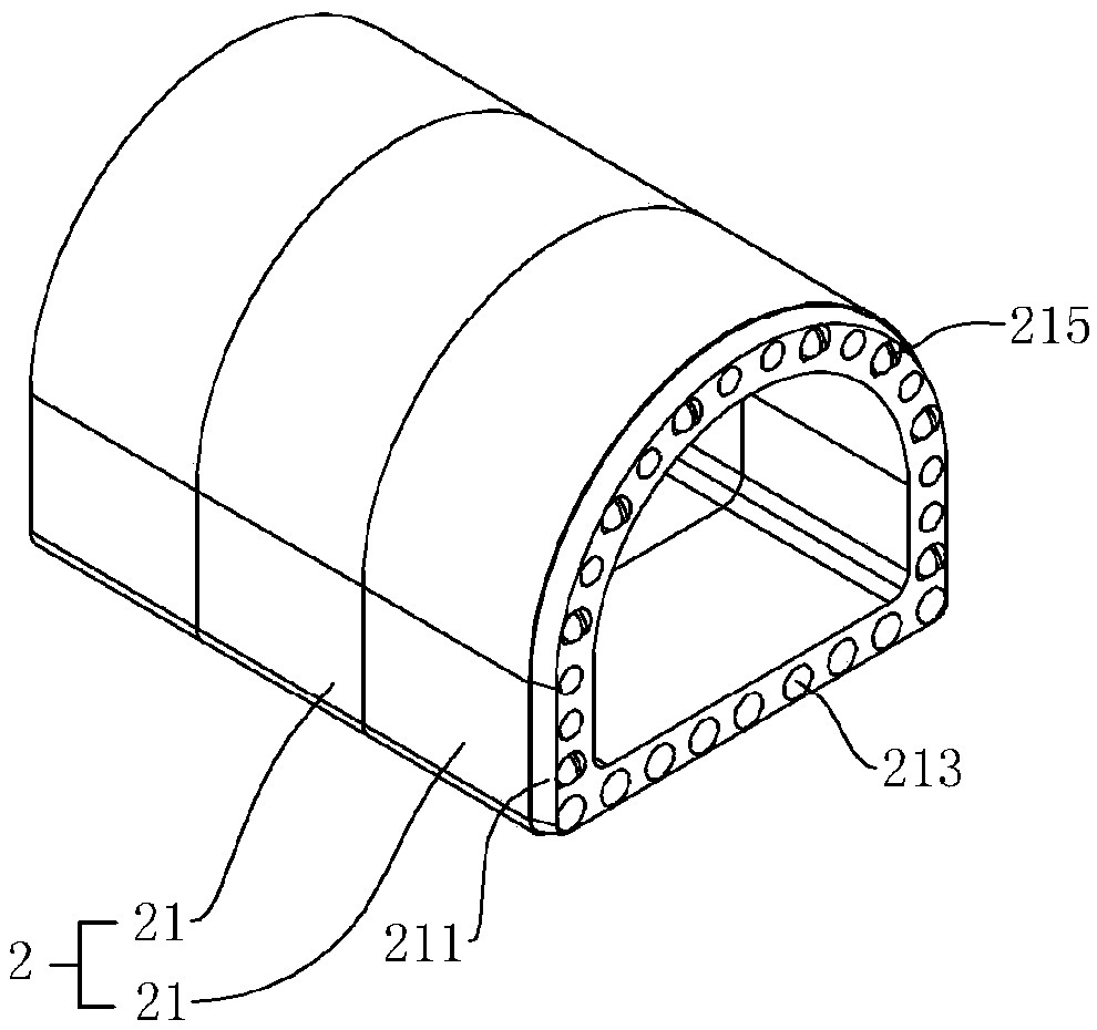
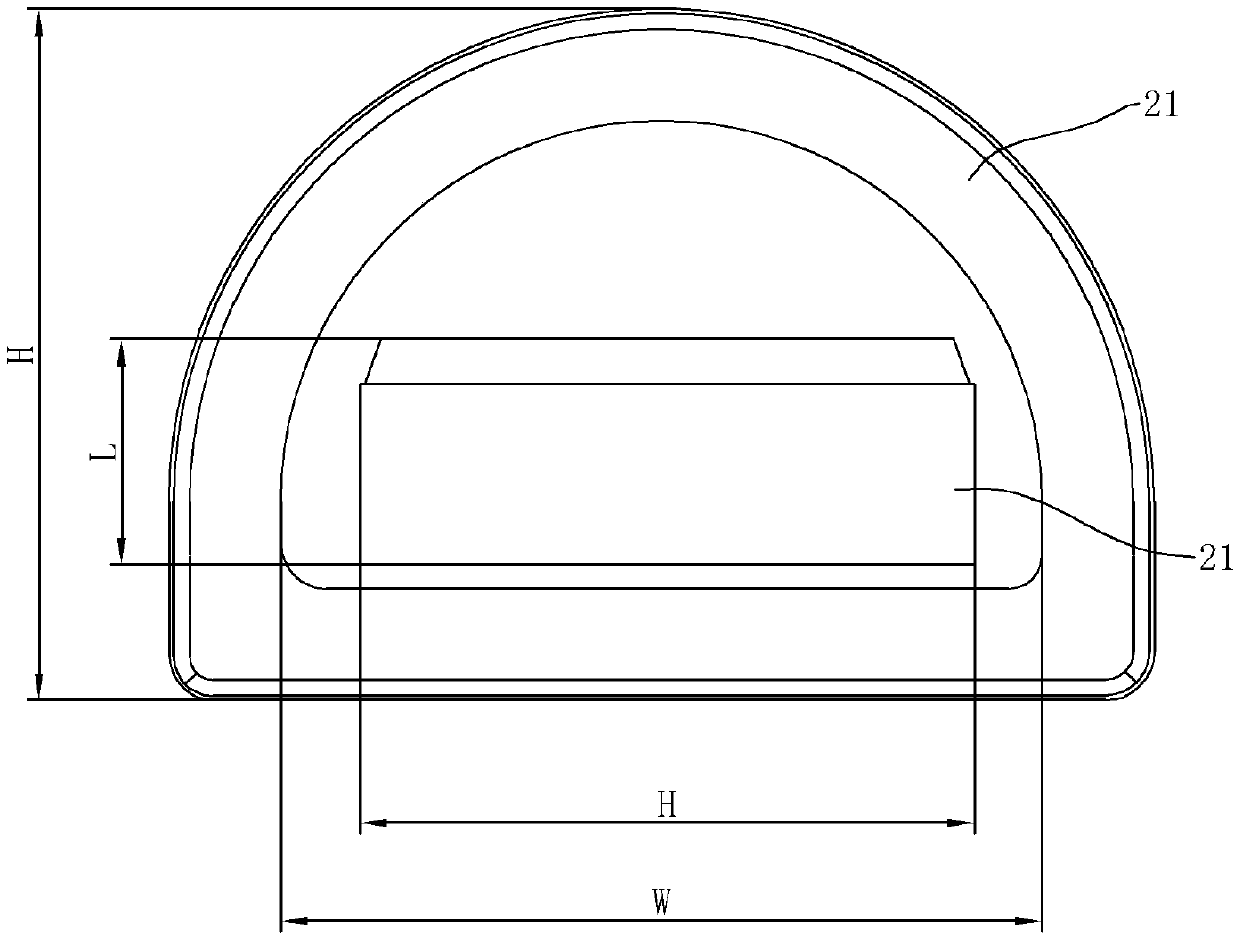
[0054] an undersea tunnel, such as figure 1 As shown, it includes a groove 1 and a lining 2, and the lining 2 is formed by splicing a prefabricated splicing module 21 along the groove 1, and the splicing module 21 is hollow tubular; combined figure 2 The distance between the bottom surface and the top surface on the outside of the splicing module 21 is less than the distance between the two sides on the inside of the splicing module 21. During the splicing process, the splicing module 21 is placed flat and rotated 90 degrees horizontally to the height direction ( figure 2 The size indicated by H in the middle is the height dimension, L refers to the length dimension, and W refers to the width dimension) is parallel to the width direction of the spliced ​​splicing module 21, and then the flat splicing module 21 is spliced ​​from the spliced Module 21 is transported inside.

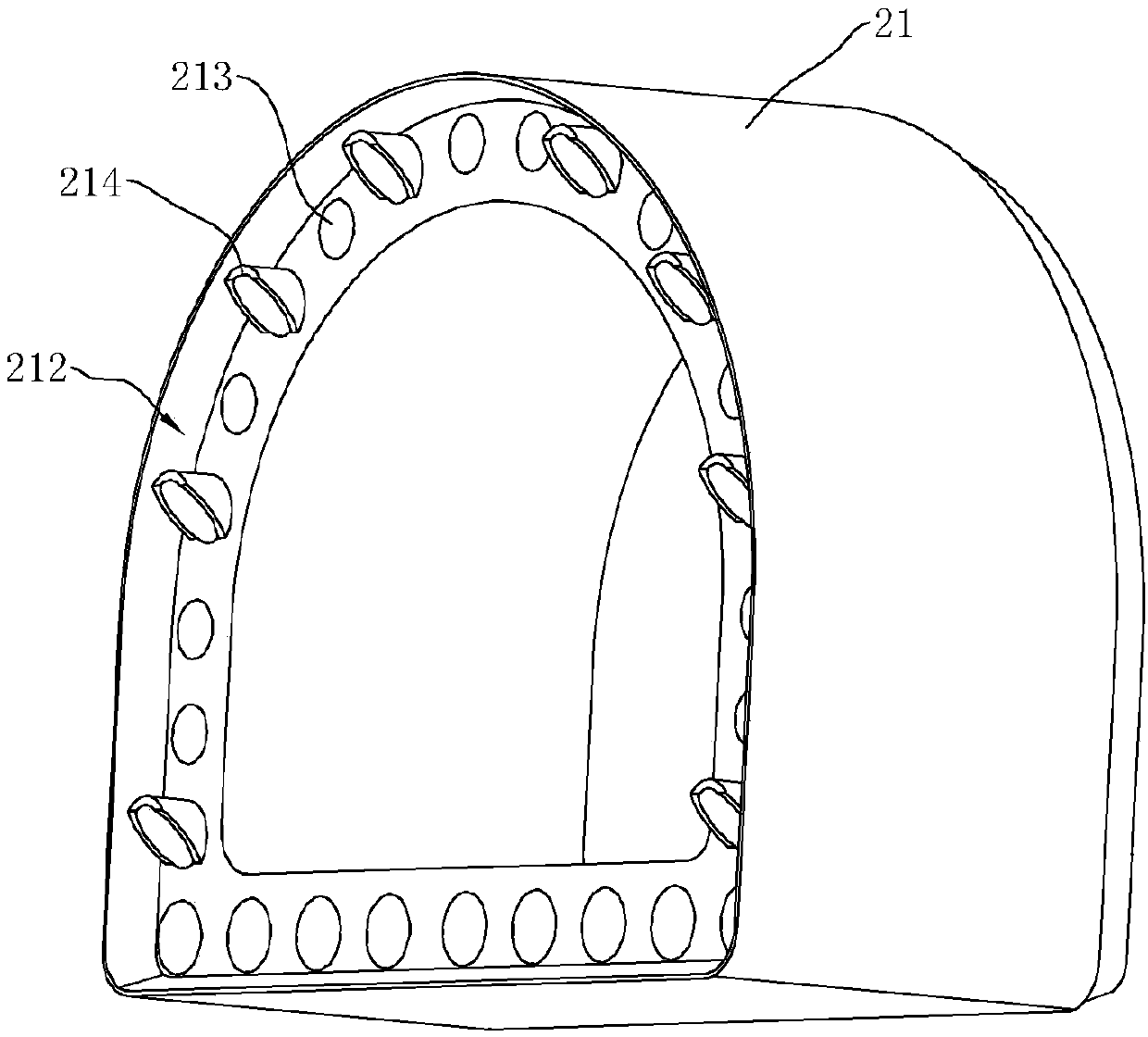
[0055] comprehensive image 3 and Figure 4 One end surface of the splicing module 21 is fixedly co...

Embodiment 2

[0059] A kind of subsea tunnel, the difference from embodiment 1 is, such as Figure 7 As shown, the inner side of the splicing module 21 is horizontally fixedly connected with a horizontal partition 216. The horizontal partition 216 can divide the tunnel into upper and lower spaces, and can be spliced ​​at one time to form two passages, which improves construction efficiency and reduces construction costs. A vertical partition 217 is fixedly connected between the upper surface of the horizontal partition 216 and the inner wall of the splicing module 21. The vertical partition 217 can divide the upper space of the horizontal partition 216 into two parallel spaces. , the air pressure in the space at the front of the train increases, and the space behind the rear of the train forms a sub-vacuum. The high pressure at the front and the low pressure at the rear hinder the advancement of the train. By connecting the two passages above the horizontal partition 216, the two passages W...

Embodiment 3

[0062] A construction method for an undersea tunnel, Figure 8 and Figure 9 (Because the length direction of the drawing is too large, in order to show the structure of the drawing more clearly, the drawing is rotated 90 degrees counterclockwise) It is a schematic diagram of the splicing process of the groove 1 and the splicing module 21, and the construction process The guide machine 3, the dredger (not shown in the figure), the berthing platform 4 and the turning machine 5 need to be used in the middle; The upper surface is provided with an inclined surface, and the inclined surface is inclined towards the bottom surface of the trench 1 along the excavation direction. When the guide machine 3 advances along the trench 1, the residual soil in the trench 1 can be pushed out of the trench 1, and it can also be enlarged. The buoyancy difference of the water that the leading machine 3 top and the bottom are subjected to prevents the leading machine 3 from floating. The tail of...


PUM


Abstract

The invention discloses an undersea tunnel and a construction method thereof. The undersea tunnel comprises a trough and a lining; the lining is composed by splicing modules which are spliced along the trough, and each splicing module is in a hollow pipe shape; and the distance between the bottom face and the top face of the outer side of each splicing module is smaller than that between the two side faces of the inner side of the splicing module. The construction method of the construction method comprises the steps that the trough is excavated in the sea bed surface through a dredger, and the splicing modules are vertically fixed into the trough; a docking platform is subsequently adopted to flatly place and rotate the splicing modules by 90 degrees and then convey the splicing modules from the inner sides of spliced splicing modules to the splicing positions; the flatly-placed splicing modules are rotated by 90 degrees, and the splicing modules are overturned through an overturningmachine to be aligned and attached to the end faces of the spliced splicing modules, and are compressed through a hydraulic cylinder; and soil excavated in the trough is backfilled to the upper facesof the spliced splicing modules. The construction efficiency is high, and the cost is low.

Description

technical field [0001] The invention relates to the technical field of tunnels, in particular to an undersea tunnel and a construction method thereof. Background technique [0002] A subsea tunnel is a tunnel opened under the seabed. There are mainly three existing subsea tunnel construction methods as follows: [0003] 1. Drilling and blasting method, first use a drilling machine to drill holes, bury explosives in the holes for blasting, gradually excavate the section to complete the excavation of the tunnel, and build the lining to prevent subsidence during the excavation process. The blasting process of this construction method has a great impact on the seawater environment, consumes a large amount of gunpowder, and needs to transport away broken stones and soil after blasting, resulting in low work efficiency and high cost. [0004] 2. Tunneling machine method, using special large-scale cutting equipment to shear, squeeze and break the rock, and then transport the crush...

Claims


Application Information

Patent Timeline
Patent Type & Authority Applications(China)
IPC IPC(8): E02D29/09E02D29/05E02D29/07
CPCE02D29/05E02D29/06E02D29/07
Inventor 郭毅轩
Owner 郭毅轩
Why Eureka
Try Eureka