
High-temperature high-pressure rear pass coal economizer mounting structure of coal power station

A high-temperature, high-pressure, installation structure technology, applied in the direction of heat exchange equipment safety devices, feed water heaters, heat exchanger shells, etc., can solve problems such as poor stability and balance, unfavorable installation and maintenance, and poor flexible adjustment, so as to ensure Structural stability, easy installation and maintenance, and the effect of reducing damage

Pending Publication Date: 2018-12-28
江阴德耐特重工科技有限公司
View PDF3 Cites 2 Cited by
  • Summary
  • Abstract
  • Description
  • Claims
  • Application Information

AI Technical Summary

Problems solved by technology

[0006] First, the fixed support installation of the economizer is not conducive to its early installation and later maintenance, and the flexibility of adjustment is poor;
[0007] Second, the hoisting structure of the economizer has poor stability and balance. It is easy to shake during use or affected by external factors, and cause safety hazards

Method used


Image

  • High-temperature high-pressure rear pass coal economizer mounting structure of coal power station
  • High-temperature high-pressure rear pass coal economizer mounting structure of coal power station
  • High-temperature high-pressure rear pass coal economizer mounting structure of coal power station

Examples


Embodiment 1

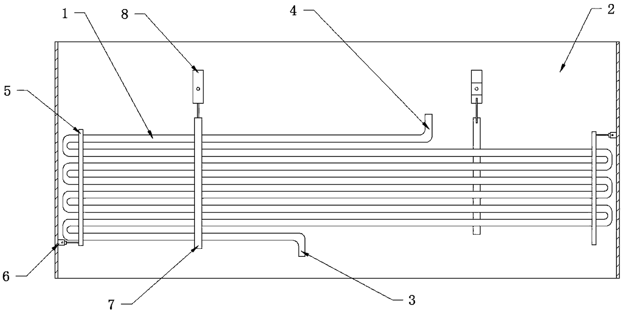
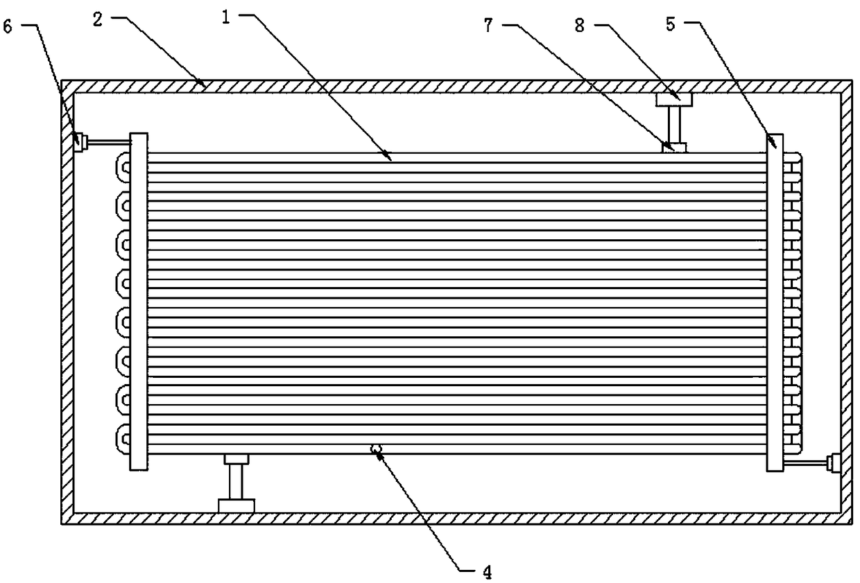
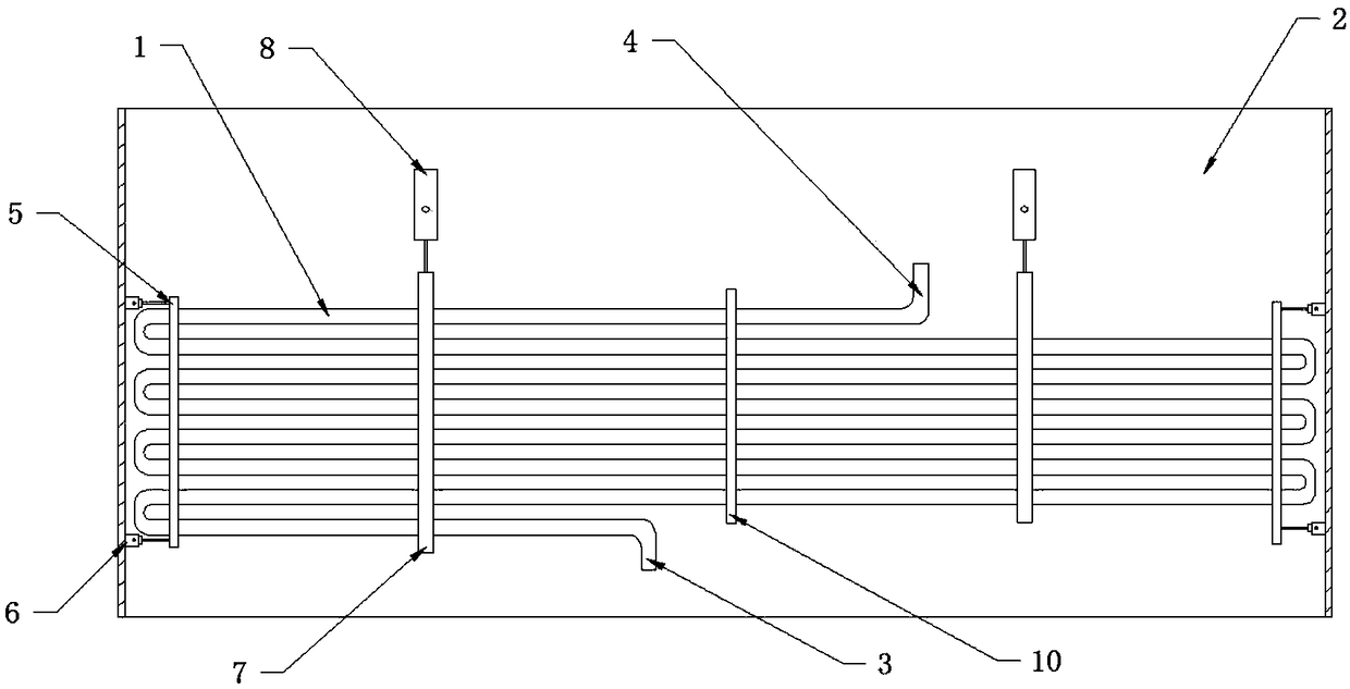
[0045] Such as figure 1 and 2 As shown, the installation structure of the high temperature and high pressure flue economizer of the power station in embodiment 1 includes the heat exchange flue 2 and the economizer hanging in the heat exchange flue 2; the economizer is composed of several rows of heat exchange The tube 1 is connected to form a heat exchange tube panel, and the heat exchange tube panel is provided with a water inlet 3 and a water outlet 4 that are connected with the water inlet main pipe and the water outlet main pipe; The swaying fixing plate 5 is vertically provided with a coordinating anti-swaying fixing mechanism 6 on the inner wall of the heat exchange flue 2, and the cooperating anti-swaying fixing mechanism 6 is connected with the anti-swaying fixing plate 5. Hanging rods 7 are vertically fixed on both sides of the heat exchange tube panel, and hanging fixtures 8 are arranged on the inner wall of the heat exchange flue.

[0046] Before installing the e...

Embodiment 2

[0048] Further optimization to embodiment 1, such as Figures 3 to 6 As shown, the difference between Embodiment 2 and Embodiment 1 is that a number of horizontal support rods 9 are arranged in the heat exchange tube panel, and a plurality of heat exchange tubes 1 of the heat exchange tube panel are supported and connected to the lateral support rods 9, and the horizontal The two ends of the support rod 9 are fixedly connected with the adjacent hanging rod 7; the anti-shake fixing mechanism 6 is connected with the upper and lower ends of the anti-shake fixing plate 5; The connecting plate 10 and the heat exchange tube 1 are passed through the opening 11 .

Embodiment 3

[0050] Further optimization to embodiment 2, such as Figures 7 to 10 As shown, the difference between embodiment 3 and embodiment 2 is that the anti-sway fixing mechanism 6 includes an anti-sway base 6-1 and an anti-sway connecting rod 6-2, and one end surface of the anti-sway base 6-1 is fixedly connected to the replacement On the inner wall of the hot flue 2, the other end of the anti-shake base 6-1 is fixedly connected to one end of the anti-shake connecting rod 6-2; the outer end of the anti-shake connecting rod 6-2 passes through the anti-shake fixing plate 5, and passes through The nut 12 is fixedly connected with the anti-sway fixed plate 5, and a gasket 13 is also arranged between the nut 12 and the anti-sway fixed plate 5; In the hole of the plate 14; between the nut 12 and the gasket 13, there is also an expansion piece 15, the expansion piece 15 is installed on the anti-shake connecting rod 6-2; the expansion piece 15 is locked between the nut 12 and the gasket 13 ...


PUM


Abstract

The invention discloses a high-temperature high-pressure rear pass coal economizer mounting structure of a coal power station. The high-temperature high-pressure rear pass coal economizer mounting structure comprises a heat exchange flue and a coal economizer hung in the heat exchange flue. The coal economizer is a heat exchange tube panel comprising a plurality of rows of communicated heat exchange tubes, the heat exchange tube panel is provided with a water inlet and a water outlet which are in fit connection with a water inlet header pipe and a water outlet header pipe respectively, shake-proof fixing plates in fit connection with the heat exchange tube are arranged on the side faces of the heat exchange tube panel, and fit shake-proof fixing mechanisms are arranged on the inner sidewalls of the heat exchange flue and are in fit connection with the shake-proof fixing plates. The high-temperature high-pressure rear pass coal economizer mounting structure of the coal power station hasthe advantages that the coal economizer can be mounted, inspected and repaired conveniently through hanging connection, and accordingly the structure is flexible to adjust; with the aid of the shake-proof structure, the coal economizer can be less prone to shaking and more reliable in structural stability, and damage caused by other external factors including earthquakes can be reduced.

Description

technical field [0001] The invention relates to the field of flue waste heat recovery, in particular to an installation structure of a high-temperature and high-pressure rear flue economizer in a power station. Background technique [0002] With the strict requirements of national energy conservation and emission reduction targets and the rising and fluctuating coal price, the cost of coal-based power generation is increasing day by day, and each power plant is facing enormous pressure for energy saving. And if the flue gas temperature at the outlet of the economizer cannot meet the minimum continuous operating temperature of normal denitrification, it will have a great impact on the subsequent treatment. Therefore, in order to effectively reduce the exhaust gas temperature of the boiler and improve the efficiency of subsequent treatment and operation economy, it is widely used in the industry to install an economizer on the exhaust flue of the boiler. [0003] Most economi...

Claims


Application Information

Patent Timeline
Patent Type & Authority Applications(China)
IPC IPC(8): F22D1/08F28F1/36F28F9/013
CPCF22D1/08F28F1/36F28F9/013F28F9/0131F28F9/0132F28F2275/20F28F2265/32
Inventor 赵文涛陈金龙黄岳军李俊谭海江赵虎谭梦磊糜晓航
Owner 江阴德耐特重工科技有限公司
Learn More