Rogowski coil and current measuring device

A Rogowski coil and coil technology, which is applied in the direction of measuring devices, only measuring current, measuring electrical variables, etc., can solve the problems of Rogowski coils with complex structures and susceptibility to environmental interference, so as to reduce interference, uniform winding, and increase induced voltage Effect

Active Publication Date: 2018-12-28
CHINA ELECTRIC POWER RES INST +2
View PDF38 Cites 9 Cited by
  • Summary
  • Abstract
  • Description
  • Claims
  • Application Information

AI Technical Summary

Problems solved by technology

[0008] The object of the present invention is to solve the problem that the existing PCB board Rogowski coil has a complex structure and is susceptible to environmental interference, and

Method used


Image

  • Rogowski coil and current measuring device
  • Rogowski coil and current measuring device
  • Rogowski coil and current measuring device

Examples


Embodiment 1

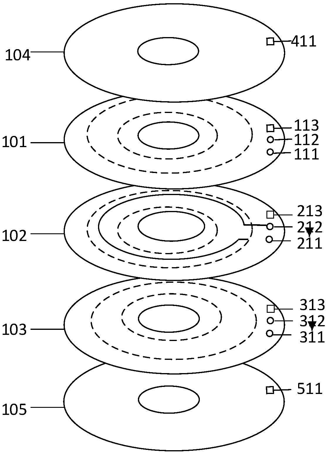
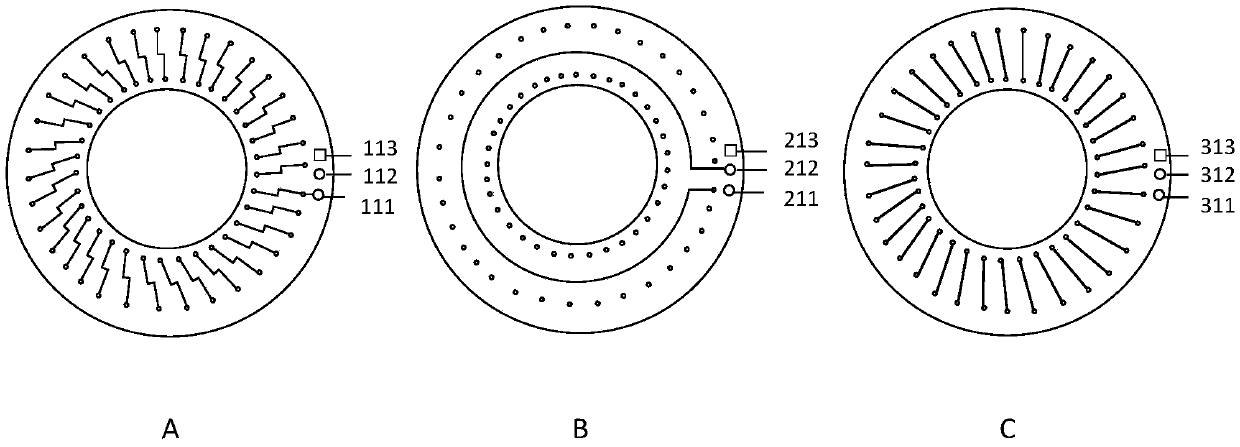
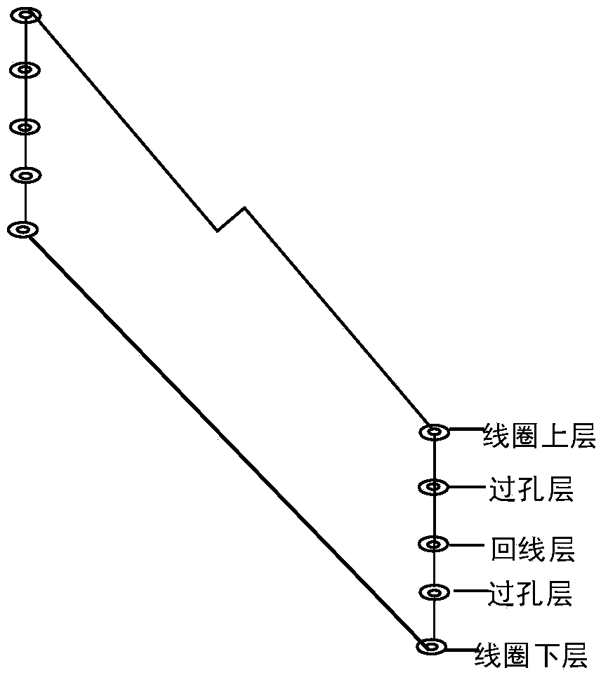
[0032] Such as figure 1As shown, a Rogowski coil in the embodiment of the present invention includes: a coil upper layer 101, including a first PCB board and metal plating, the first PCB board is provided with a plurality of conductive through holes, and the plurality of conductive through holes are uniform Arranged and aligned along the radial direction to form a ring, the conductive through holes of the annular inner ring are obliquely connected to the conductive through holes of the annular outer ring through the metal plating; the loop layer 102 includes the second PCB board and Metal electroplating, the second PCB board is provided with a plurality of conductive through holes, the plurality of conductive through holes are evenly arranged, aligned along the radial direction to form a ring, and the metal electroplating is plated on the second PCB in a circle. On the middle board surface of the annular conductive through hole of the PCB board; the lower layer 103 of the coil...

Embodiment 2

[0045] Based on Example 1, such as Figure 4 As shown, the embodiment of the present invention is a current measuring device, including the Rogowski coil 001 described in the first embodiment. Wherein, it also includes: a signal processing module 002, which is connected with the Rogowski coil 001 through a coaxial measurement cable, and is used for collecting measurement data and calculating waveform parameters of the measurement data.

[0046] In this example, if Figure 5 and Figure 6 As shown, the signal processing module 002 includes: a data acquisition unit 023, which is used to convert the analog signal of the measurement data into a digital signal for easy analysis and calculation; a calculation and analysis unit 024, which is used to calculate the peak value of the waveform of the measurement data and the calculated Describes the time parameter of the waveform of the measurement data.

[0047] As a preferred embodiment, such as Figure 5 As shown, the signal proce...

Embodiment 3

[0053] Such as Figure 7 As shown, in a specific embodiment of the present invention, a current i(t) flows through the measured metal electroplating object, and an induced voltage is generated in the Rogowski coil 11. After the induced voltage is integrated by the integrating circuit, the second circuit through the second PCB board The output hole is output to the coaxial cable, and then the integrated induced voltage is transmitted to the data acquisition unit 41 through the coaxial cable (31, 32, 33). In order to reduce the influence of the external electric field or magnetic field on the induced voltage, a shielding layer 12 is used outside the Rogowski coil 11, and two shielding layers are arranged outside the coaxial cable core wire 31: the outer shielding layer 33 of the cable, the inner shielding layer 32 of the cable, and the outer shielding layer 32 of the cable. The outer shielding layer 33 is connected to the shielding layer 12, and the data acquisition unit shieldi...


PUM


Abstract

The invention discloses a Rogowski coil and a current measuring device, and belongs to the field of current transformers. A Rogowski coil of the present invention comprises an upper layer of a coil, aloop layer and a lower layer of the coil, wherein the upper layer of a coil, the loop layer and the lower layer of the coil are provided with a plurality of conductive through-holes and metal platingmaterials. The plurality of conductive through-holes are evenly arranged and aligned in a radial direction to form a ring shape. The conductive through-holes of the annular inner ring of the upper layer of a coil are obliquely connected to the conductive through-holes of the annular outer ring by the metal plating materials. The metal plating materials of the loop layer are annularly formed and plated in the middle of the annular conductive through-holes. The conductive through-holes of the annular inner ring of the lower layer of the coil are radially connected to the conductive through-holes of the annular outer ring by the metal plating materials. The metal plating materials and the through-holes form a loop coil. According to the Rogowski coil and current measuring device, a multi-layer PCB is set on the Rogowski coil, the thickness of the Rogowski coil is increased, so that the mutual inductance coefficient of the Rogowski coil, which is the induced voltage of the output, is increased, the sensitivity coefficient of the coil is increased, which is advantageous for current measurement of a lower amplitude.

Description

technical field [0001] The present invention relates to a current transformer, and more particularly, to a Rogowski coil and a current measuring device. Background technique [0002] Traditional switching devices for pulsed current measurements include shunts and Rogowski coils (Rogowski coils). The shunt is suitable for measuring the pulse current with a narrow pulse width below 100kA; the shunt is a metal film resistor, and the structure includes a strip-folded type, a coaxial type, a disc type, etc., and the design idea is to reduce the stray inductance as much as possible. If the voltage amplitude is large, the pulse width is very wide or the installation position is limited, Rogowski coils are generally used as current conversion devices; traditional Rogowski coils are based on the principle of electromagnetic induction, and the enameled wire is wound on an insulating skeleton or iron core. When the current in the center of the coil passes through, An induced voltage w...

Claims


Application Information

Patent Timeline
IPC IPC(8): G01R19/00G01R19/25G01R15/18
CPCG01R15/18G01R19/0092G01R19/25
Inventor 龙兆芝刘少波李文婷王晖南张弛肖凯
Owner CHINA ELECTRIC POWER RES INST
Why Eureka
Try Eureka