Oil well thermal washing and paraffin removal device

A technology of hot washing and wax removal, which is applied to cleaning equipment, wellbore/well parts, earthwork drilling and production, etc. It can solve problems such as affecting production, wasting energy, explosion, etc., and achieves fuel saving, convenient transportation and safe process operation Effect

Inactive Publication Date: 2019-01-01
西安瑞杰实业股份有限公司
View PDF0 Cites 0 Cited by
  • Summary
  • Abstract
  • Description
  • Claims
  • Application Information

AI Technical Summary

Problems solved by technology

[0003] This method requires 20-30 square meters of water, which is a large amount of water. After heating the water and injecting it into the oil well, it will not only pollute the oil layer, but also cause well killing, that is, it will take several days to discharge them when the oil well is in production. , affecting output and causing waste
This kind of heating furnace uses the flame to directly heat the furnace tube, the thermal efficiency is low, and the fuel it uses is diesel oil, so the consumption of diesel oil is relatively large, which not only wastes energy, but also pollutes the air
In addition, if the method of heating the output fluid of the oil well to re-inject the ring sleeve is used to remove wax, sometimes the oil well will produce oil intermittently. At this time, the heating furnace is likely to burn the coil in the furnace red and cause an explosion, so there is also a greater safety hazard. Hidden danger
Some oil wells need to operate for a long time. In order to save a vehicle, after the heating furnace is transported to the oil well, the heating furnace is unloaded from the vehicle and the vehicle can be driven away, but this requires an additional crane , when the work is completed, the heating furnace is hoisted to the truck with a crane to pull it away, which increases the workload of the crane and is also very troublesome

Method used


Image

  • Oil well thermal washing and paraffin removal device
  • Oil well thermal washing and paraffin removal device
  • Oil well thermal washing and paraffin removal device

Examples


Embodiment Construction

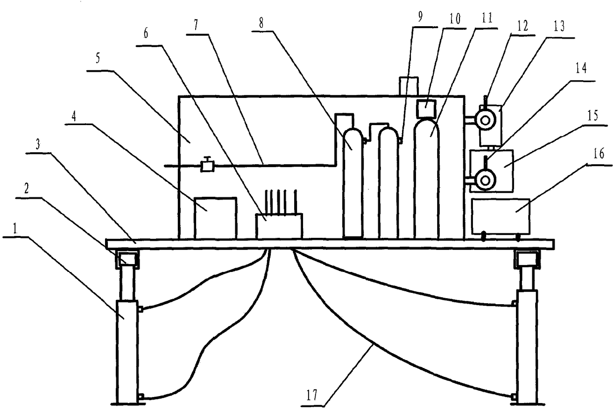
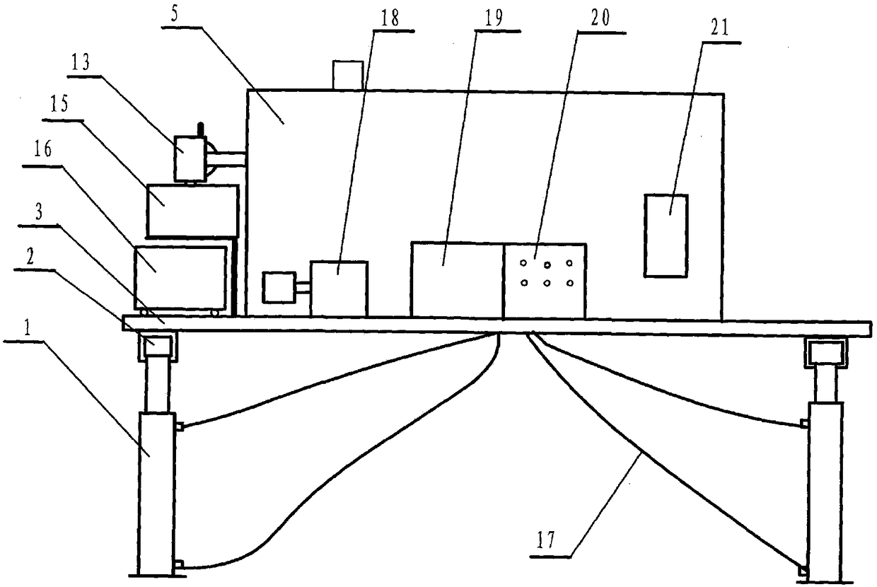
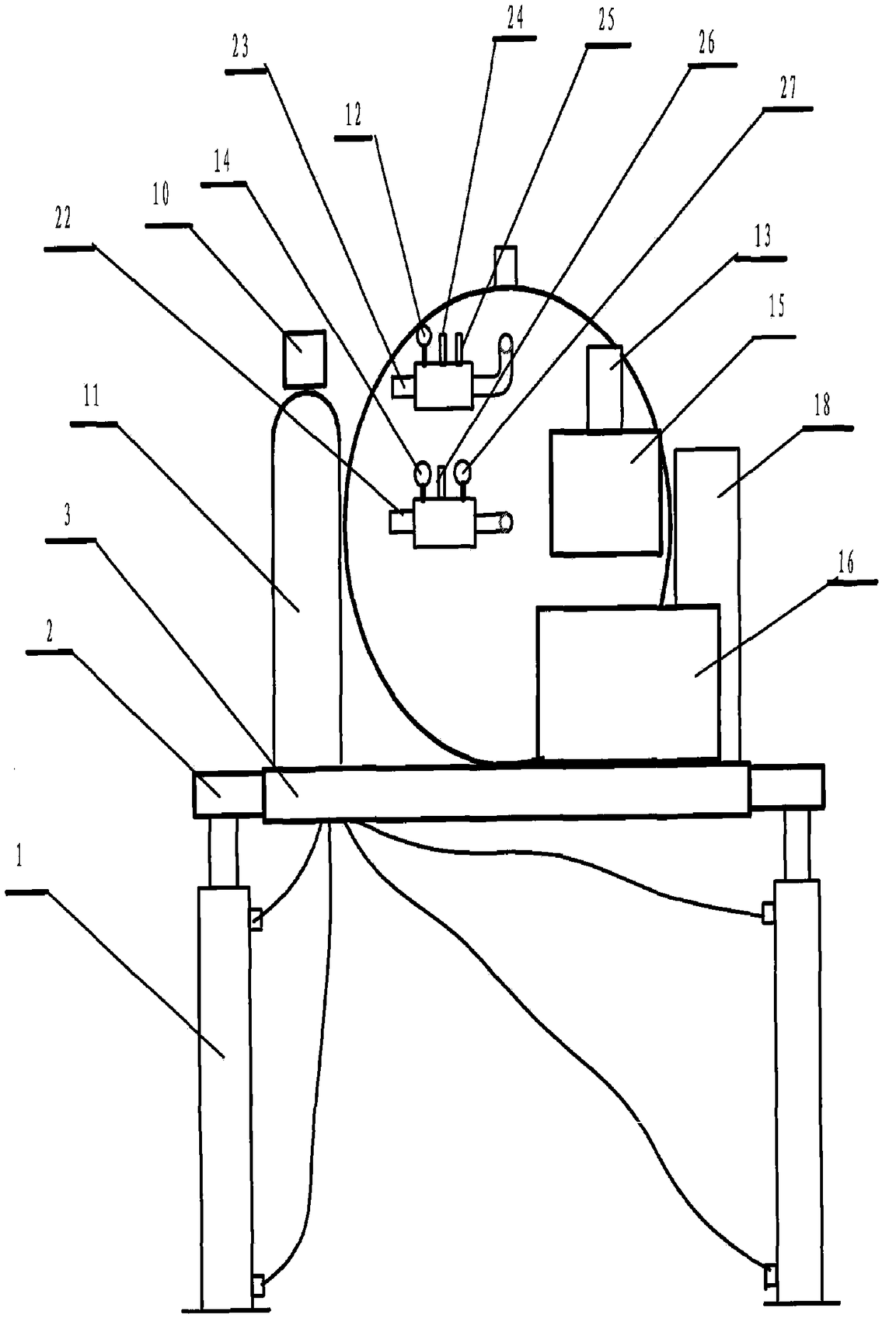
[0014] The present invention will be described in detail below in conjunction with the accompanying drawings.

[0015] Such as Figure 1~3 As shown, the oil well thermal wax removal device provided by the present invention includes a base plate 3, a heating furnace 5 is installed in the middle of the base plate 3, and a natural gas purification tank 8, a softened water tank 11, a plunger pump 18, an intelligent Control box 19, power switchboard 20, hydraulic control valve 6; telescopic rod 2 is installed on the four corners of bottom plate 3, and hydraulic prop 1 is installed under the end of each telescopic rod 2, and wheels are installed on the bottom of hydraulic prop 1, and wheels are installed on the wheels. There is a fixed clamping device; the hydraulic pump is connected with the motor 13 through the shaft, the motor 13 is installed on the oil tank 15, the oil tank is installed on the bottom plate, the outlet of the hydraulic pump is connected with the inlet of the hydr...


PUM


Abstract

The invention discloses an oil well thermal washing and paraffin removal device. A heating furnace is installed on a bottom plate, and a telescopic rod and a hydraulic pillar are mounted on the bottomplate, or wheels are mounted on the bottom plate. A hydraulic control valve, a natural gas purification tank, a water softening device, a plunger pump, an intelligent control box and a power distribution board are installed on the bottom plate, an inlet of the plunger pump and the water softening device are connected, an outlet of the plunger pump is connected with an inlet of the heating furnace, and an electric motor is connected with a power source through a frequency converter. The hydraulic control valve is connected with the hydraulic pillar; an outlet temperature sensor and a pressuresensor are installed at an outlet of the heating furnace, and are connected with a temperature controller, a printer pressure display printer and a control power source by wires. The natural gas purification tank and a gas inlet of the heating furnace are connected. The oil well thermal washing and paraffin removal device has the beneficial effects that a crane is not needed, self-loading and unloading are realized, and associated gas fuel is used as fuel, the fuel is saved, the process operation is safe, and the production life of the oil well is prolonged.

Description

technical field [0001] The invention relates to an oil well cleaning device, in particular to an oil well thermal wax removal device. Background technique [0002] In the crude oil production process of the prior art, the wax contained in the crude oil will continuously precipitate and condense on the oil pipe wall. After a long time, the oil pipe will be blocked. Therefore, the wax removal work should be carried out after a period of time. In the past, a special wax removal car was used, that is, a heating furnace was installed on one car, and a water tank car was equipped in addition. The two cars went to the oil well site together, and the water was heated by the heating furnace and injected into the oil well ring. Heat the oil pipe inside the sleeve to melt the wax accumulated in the oil pipe. [0003] This method requires 20-30 square meters of water, which is a large amount of water. After heating the water and injecting it into the oil well, it will not only pollute ...

Claims


Application Information

Patent Timeline
Patent Type & Authority Applications(China)
IPC IPC(8): E21B37/00
CPCE21B37/00
Inventor 曹雅丽
Owner 西安瑞杰实业股份有限公司
Why Eureka
Try Eureka