
Electric oil pump assembly, steering system and lubricating system

An electric oil pump and assembly technology, which is applied in the field of lubrication systems, can solve the problems of large volume of electric oil pumps, complex structure of damping elements, high noise of motor operation, etc., achieve high level of light weight, improve heat dissipation performance and work stability , the effect of high integration

Active Publication Date: 2019-01-01
BYD CO LTD
View PDF10 Cites 3 Cited by
  • Summary
  • Abstract
  • Description
  • Claims
  • Application Information

AI Technical Summary

Problems solved by technology

[0002] Electric oil pumps are widely used in the steering system and lubrication system of vehicles. In related technologies, the oil pump and the motor of the electric oil pump are separated, and the connection relationship is only the dynamic coupling connection between the oil pump shaft and the motor shaft, which makes the electric oil pump larger. , takes up a lot of installation space
In addition, the operating noise of the motor and the oil pump are relatively loud. In related technologies, various damping elements are often used to isolate the noise. The structure of the damping element is complex, occupying a large installation space, and the production cost is high and the assembly process is complicated. room for improvement

Method used


Image

  • Electric oil pump assembly, steering system and lubricating system
  • Electric oil pump assembly, steering system and lubricating system
  • Electric oil pump assembly, steering system and lubricating system

Examples


Embodiment 1

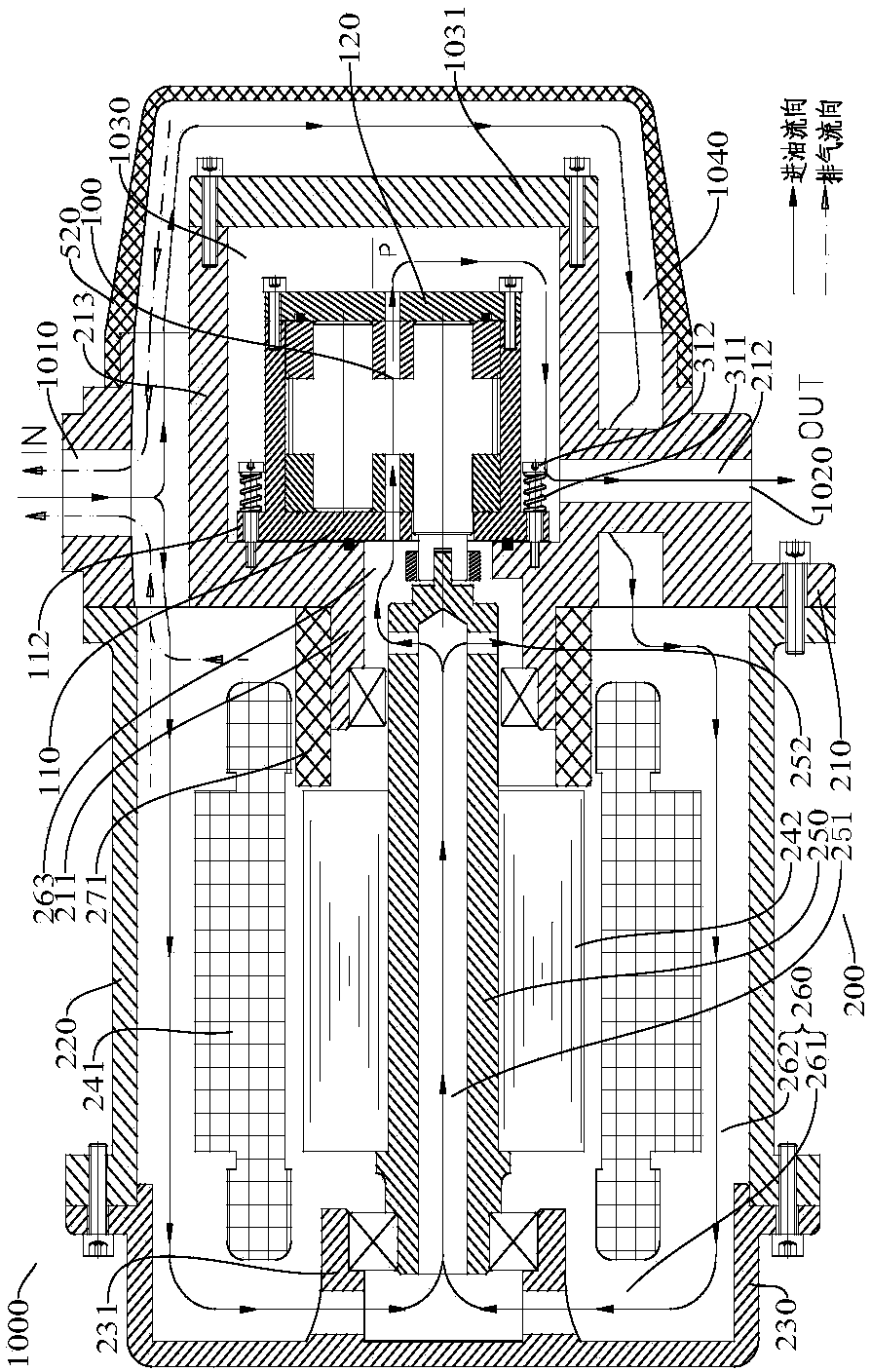
[0061] Such as figure 1 , Figure 4 , Figure 5 , Figure 10 , Figure 13 , Figure 14 , Figure 19 , Figure 21 , Figure 22 , Figure 24 , Figure 26 , Figure 27 , Figure 29 , Figure 31 , Figure 32 , Figure 34 , Figure 36 , Figure 37 , Figure 39 As shown, an electric oil pump assembly 1000 according to an embodiment of the present invention includes: a motor assembly 200 and an oil pump assembly 100 .

[0062] Wherein, the oil pump assembly 100 is dynamically coupled with the motor shaft 250, and the motor assembly 200 is used to provide the driving force for the operation of the oil pump assembly 100. For example, the motor shaft 250 of the motor assembly 200 can be connected with the oil pump shaft 130 of the oil pump assembly 100 through a coupling 410. Of course, the motor assembly 200 is not limited to directly driving the oil pump assembly 100 , and can also be connected to the oil pump assembly 100 through a transmission mechanism such as a g...

Embodiment 2

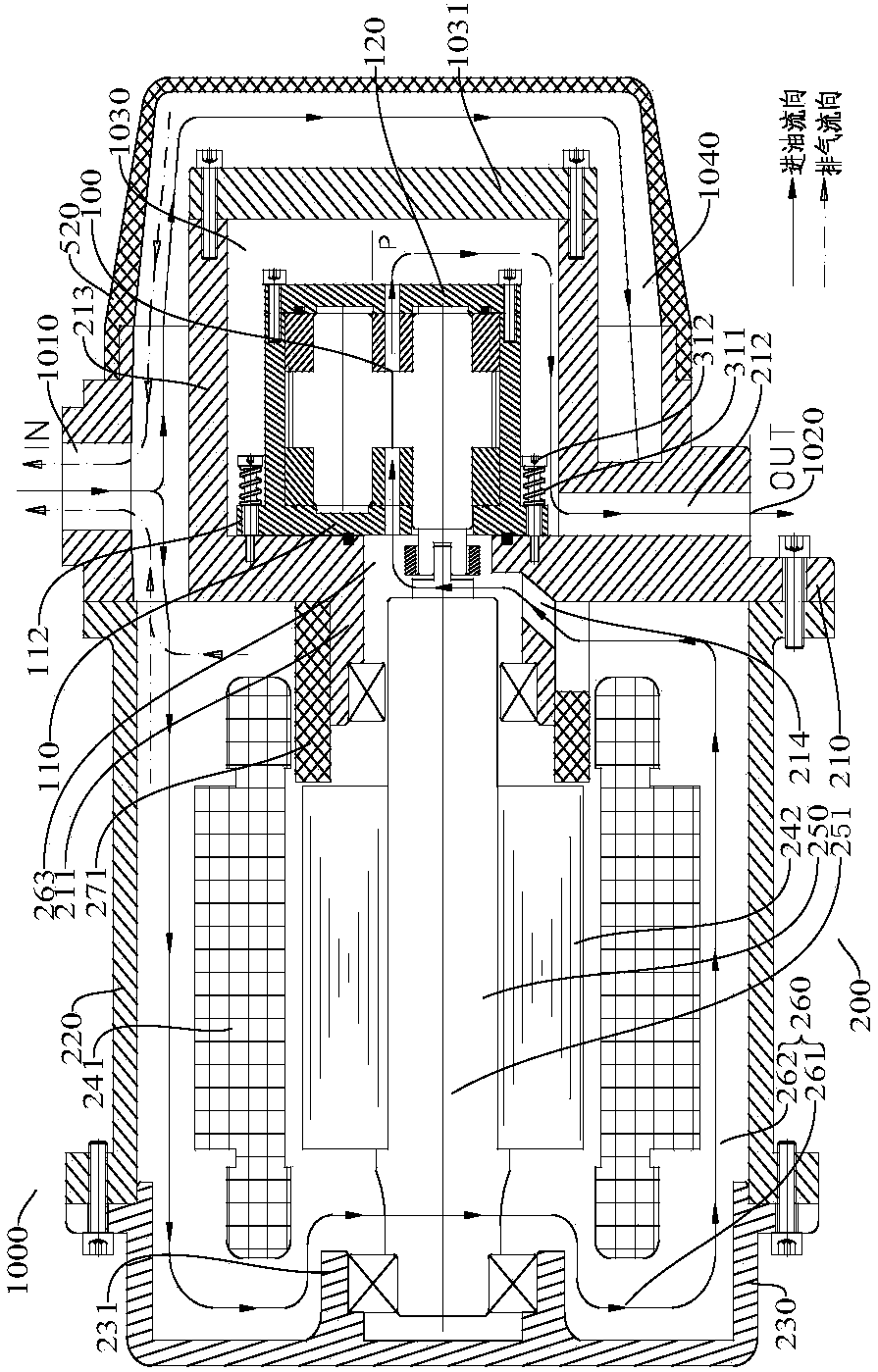
[0084] Such as figure 2 , Figure 6 , Figure 7 , Figure 11 , Figure 15 , Figure 16 , Figure 20 , Figure 23 , Figure 25 , Figure 28 , Figure 30 , Figure 33 , Figure 35 , Figure 38 , Figure 40 As shown, an electric oil pump assembly 1000 according to an embodiment of the present invention includes: a motor assembly 200 and an oil pump assembly 100 .

[0085] Wherein, the oil pump assembly 100 is dynamically coupled with the motor shaft 250, and the motor assembly 200 is used to provide the driving force for the operation of the oil pump assembly 100. For example, the motor shaft 250 of the motor assembly 200 can be connected with the oil pump shaft 130 of the oil pump assembly 100 through a coupling 410. Of course, the motor assembly 200 is not limited to directly driving the oil pump assembly 100 , and can also be connected to the oil pump assembly 100 through a transmission mechanism such as a gearbox or a reducer.

[0086] The oil pump assembly 100...

Embodiment 3

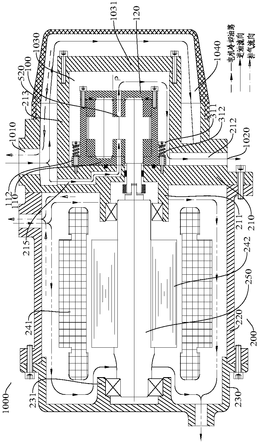
[0105] Such as image 3 , Figure 8 , Figure 9 , Figure 12 , Figure 17 , Figure 18 As shown, an electric oil pump assembly 1000 according to an embodiment of the present invention includes: a motor assembly 200 and an oil pump assembly 100 .

[0106] Wherein, the oil pump assembly 100 is dynamically coupled with the motor shaft 250, and the motor assembly 200 is used to provide the driving force for the operation of the oil pump assembly 100. For example, the motor shaft 250 of the motor assembly 200 can be connected with the oil pump shaft 130 of the oil pump assembly 100 through a coupling 410. Of course, the motor assembly 200 is not limited to directly driving the oil pump assembly 100 , and can also be connected to the oil pump assembly 100 through a transmission mechanism such as a gearbox or a reducer.

[0107] The oil pump assembly 100 works under the drive of the motor assembly 200 to convert the low-pressure oil into high-pressure oil output. The oil pump as...


PUM


Abstract

The invention discloses an electric oil pump assembly, a steering system and a lubricating system. The electric oil pump assembly is provided with a total oil inlet and a total oil outlet, and comprises a motor assembly and an oil pump assembly, wherein the motor assembly is provided with a liquid cooling cavity which is in communication with the total oil inlet, the liquid cooling cavity comprises circulating oil channels, and the circulating oil channels are located between a stator of the motor assembly and a motor shell of the motor assembly; the oil pump assembly is installed at the end part of the motor assembly and is in power coupling connection with a motor shaft of the motor assembly; and an oil suction port of the oil pump assembly is in communication with the circulating oil channels, and an oil discharge port of the oil pump assembly is in communication with the total oil outlet. According to the electric oil pump assembly, the oil absorption of the oil pump assembly and the heat dissipation of the motor assembly are realized through the arrangement of the circulating oil channels, the heat dissipation performance and the working stability of the electric oil pump assembly are improved, the integration degree is high, and the light weight level is high.

Description

technical field [0001] The invention belongs to the technical field of vehicle manufacturing, and in particular relates to an electric oil pump assembly, a steering system with the electric oil pump assembly and a lubricating system with the electric oil pump assembly. Background technique [0002] Electric oil pumps are widely used in the steering system and lubrication system of vehicles. In related technologies, the oil pump and the motor of the electric oil pump are separated, and the connection relationship is only the dynamic coupling connection between the oil pump shaft and the motor shaft, which makes the electric oil pump larger. , takes up a lot of installation space. In addition, the operating noise of the motor and the oil pump are relatively loud. In related technologies, various damping elements are often used to isolate the noise. The structure of the damping element is complex, occupying a large installation space, and the production cost is high and the ass...

Claims


Application Information

Patent Timeline
Patent Type & Authority Applications(China)
IPC IPC(8): F04B17/03F04B53/22F04B53/00F04B53/08F04C11/00F04C15/00H02K7/14H02K9/19F01M1/02B62D5/06
CPCH02K7/14H02K9/19F01M1/02F04B17/03F04B53/00F04B53/002F04B53/08F04B53/22F04C11/008F04C15/00F04C15/008F04C15/0096B62D5/064F01M2001/0215B62D5/06F04C11/00
Inventor 杨胜麟刘彦王涛
Owner BYD CO LTD
Learn More