
High-precision phase difference measurement method and circuit

A measurement method and phase difference technology, applied in the direction of measuring electrical variables, measuring devices, and the phase angle between voltage and current, can solve the problems of low measurable frequency, low measurement accuracy, and inability to measure high-frequency signals, etc. The effect of simple circuit, high measurement accuracy and high signal frequency

Active Publication Date: 2019-01-01
SHANDONG JIAOTONG UNIV
View PDF11 Cites 5 Cited by
  • Summary
  • Abstract
  • Description
  • Claims
  • Application Information

AI Technical Summary

Problems solved by technology

[0003] The existing phase difference measurement methods have different shortcomings. The oscilloscope measurement method is limited by human reading factors, and the measurement accuracy is low; the voltage measurement method based on the XOR gate is limited by the operating frequency of the XOR gate chip, and cannot measure tens of The high-frequency signal above MHz, and the measurement accuracy is not high enough; the measurement accuracy of the pulse counting method based on the XOR gate has been improved, but the performance requirements of the front-end circuit are too high, and it is affected by the work of the XOR gate chip, counter, and MCU. Frequency limit, lower measurable frequency

Method used


Image

  • High-precision phase difference measurement method and circuit
  • High-precision phase difference measurement method and circuit
  • High-precision phase difference measurement method and circuit

Examples


Embodiment Construction

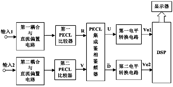
[0026] With reference to the drawings, the high-precision phase difference measurement method of the present invention is performed according to the following steps:

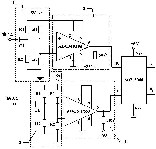
[0027] a. Choose a PECL integrated phase detector MC12040, whose two pulse input terminals are R and V respectively.

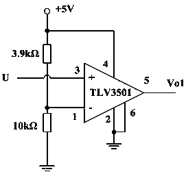
[0028] b. Introduce one of the two input signals to be tested from the input 1 terminal, after passing through the first coupling and DC bias circuit, input to the non-inverting input terminal of the first PECL comparator ADCMP553, the inverting of the first PECL comparator The input terminal is connected to a fixed level, and the output terminal 6 of the comparator is connected to the input terminal R of the phase detector MC12040. The other input signal to be tested is introduced from the input 2 terminal, after passing through the second coupling and DC bias circuit, it is input to the non-inverting input terminal of the second PECL comparator ADCMP553, and the inverting input terminal of the comp...


PUM


Abstract

The invention, which belongs to the technical field of electronic measurement, in particular relates to a high-precision phase difference measurement method and circuit. A high-speed comparator is used for carrying out shaping on two paths of signals; a high-frequency integrated phase discrimination and frequency discrimination device carries out phase comparison to obtain a phase difference pulse; after level conversion, DSP qualitative determination, initial measurement and error correction are carried out to obtain accurate phase difference parameters of the two paths of signals and then the parameters are displayed. With comprehensive utilization of the high-speed phase-discrimination technology and the DSP's fast calculation and processing, accurate measurement of the phase differenceparameters between the two paths of same-frequency input signals in the wide frequency range is realized.

Description

Technical field [0001] The invention relates to a phase difference measurement technology in the field of electronic measurement technology, in particular to a high-precision phase difference measurement method and circuit. Background technique [0002] In the fields of communications, instrumentation, etc., in order to achieve specific purposes, it is often necessary to measure the phase difference between two signals of the same frequency. There are many existing phase difference measurement methods. The most basic measurement method is to use an oscilloscope to measure, and it can also use a voltage measurement method based on an exclusive OR gate or a pulse counting method. [0003] The existing phase difference measurement methods have different shortcomings. The oscilloscope measurement method is limited by man-made reading factors, and the measurement accuracy is low; the voltage measurement method based on the XOR gate is limited by the operating frequency of the XOR gate c...

Claims


Application Information

Patent Timeline
IPC IPC(8): G01R25/08
CPCG01R25/08
Inventor 司朝良钟凌惠饶中洋
Owner SHANDONG JIAOTONG UNIV
Learn More