
Three-port DC power electronic transformer

A technology of power electronics and transformers, which is applied in the direction of adjusting electric variables, converting DC power input to DC power output, instruments, etc., can solve the problems that cannot meet the needs of power distribution system and user side, and achieve easy expansion and redundant design, Reduce costs and facilitate system maintenance

Pending Publication Date: 2019-01-01
TBEA SUNOASIS +1
View PDF0 Cites 6 Cited by
  • Summary
  • Abstract
  • Description
  • Claims
  • Application Information

AI Technical Summary

Problems solved by technology

[0003] At present, most of the DC transformers are of two-port structure, which mainly realizes the power transmission and conversion from medium and high voltage DC to a single low voltage DC bus. With the increasingly complex power distribution network and the increase of DC loads of different voltage levels, this The two-port DC transformer network has gradually failed to meet the needs of the power distribution system and the user side

Method used


Image

  • Three-port DC power electronic transformer
  • Three-port DC power electronic transformer
  • Three-port DC power electronic transformer

Examples


Embodiment Construction

[0020] The present invention will be described in detail below in conjunction with the accompanying drawings and specific embodiments.

[0021] Illustrate the complete steps of the inventive method:

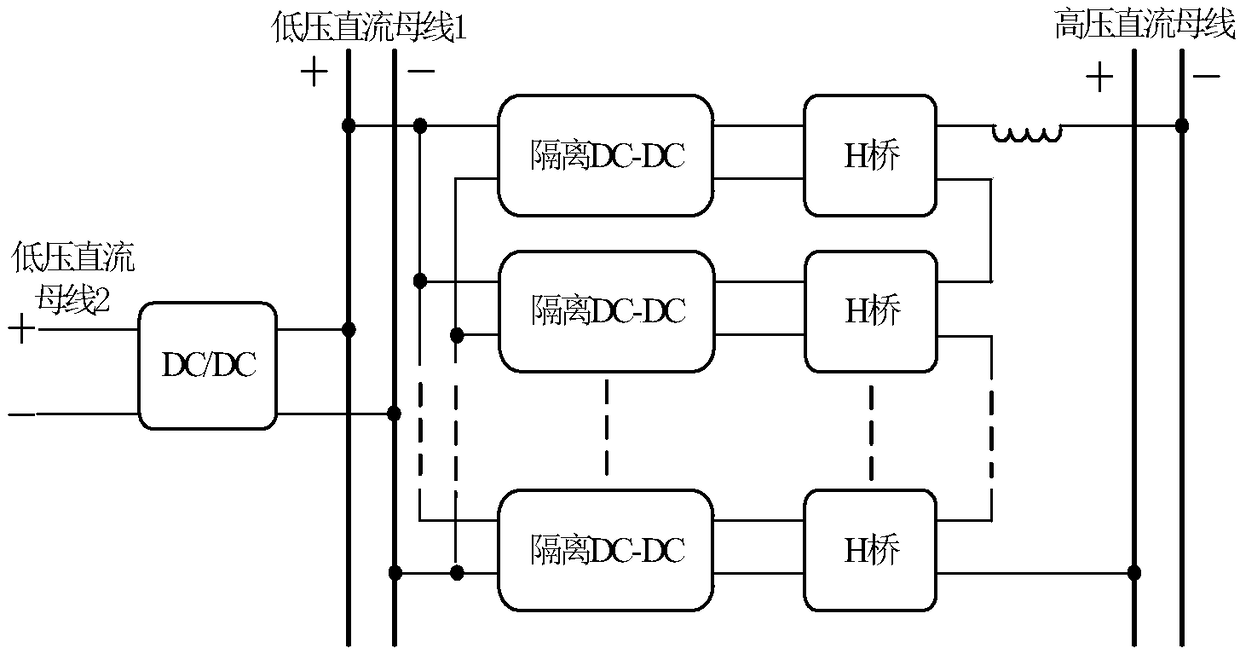
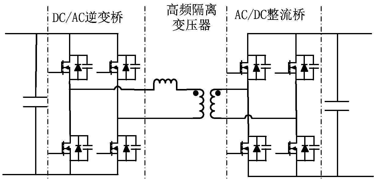
[0022] figure 1 Shown is a three-port DC power electronic transformer circuit structure diagram, including filter inductors, multiple high-frequency isolated DC-DC converters, multiple H-bridge inverter units and a low-voltage non-isolated DC-DC converter. The low-voltage DC input side of multiple high-frequency isolated DC-DC converters is connected in parallel, the positive pole is connected to the positive pole of the low-voltage DC bus 1, the negative pole is connected to the negative pole of the low-voltage DC bus 1, and the high-voltage DC output side of the high-frequency isolated DC-DC converter is connected to the H bridge The DC input side of the inverter unit is connected, the inverter side of multiple H-bridge inverter units, that is, the AC output side, is connected...


PUM


Abstract

The invention discloses a three-port DC power electronic transformer, and the transformer comprises a filter inductor, a plurality of high-frequency isolated DC-DC converters, a plurality of H-bridgeinverter units and a low-voltage non-isolated DC-DC converter. The low- voltage DC input sides of the plurality of high-frequency isolated DC-DC converters are connected in parallel to form one of thelow-voltage DC ports, and the low-voltage DC port is connected to one of the low-voltage DC busses. The high-voltage DC output side of each high-frequency isolated DC-DC converter is connected with the DC input side of the corresponding H-bridge inverter unit, and the AC output sides of the H-bridge inverter units are connected in series to form a high-voltage DC port, and the high-voltage DC port is connected to a high-voltage DC bus. A filter inductor is connected between the negative electrode of the high voltage DC bus and the AC output side of the H-bridge inverter unit. The output sideof the low-voltage non-isolated DC-DC converter and the low-voltage DC input sides of the high-frequency isolated DC-DC converters are connected in parallel, and the input side is connected with the other low-voltage DC bus to form the other low-voltage DC port. The transformer can be used as an interface system for three different voltage-level DC transmission and distribution networks.

Description

technical field [0001] The invention belongs to the technical field of power electronic transformers, in particular to a three-port DC power electronic transformer. Background technique [0002] With the rapid development of distributed power and the rapid increase of DC load, the traditional AC grid structure cannot meet the development needs of the future grid. The multi-terminal DC transmission system and DC bus technology based on conventional DC and flexible DC are the key to solving this problem. . DC distribution network has better performance than AC distribution network technology in terms of transmission capacity, controllability, improvement of power supply quality, reduction of line loss, isolation of AC and DC faults, and flexible and convenient access of renewable energy. However, in DC power transmission and distribution, the voltage conversion and power flow between grids of different DC voltage levels cannot be realized like the AC magnetic coupling method ...

Claims


Application Information

Patent Timeline
Patent Type & Authority Applications(China)
IPC IPC(8): H02M3/335H02M3/158
CPCH02M3/1584H02M3/33569
Inventor 段飞跃刘韬郝翔
Owner TBEA SUNOASIS
Learn More