
Coating blade for steel component processing and preparing method thereof

A technology for coating blades and steel parts, which is applied in metal processing equipment, coatings, metal material coating processes, etc., can solve problems such as built-up edge and crater wear of coated blades, and achieve sharpness and fineness Grain size, the effect of improving the service life

Active Publication Date: 2019-01-04
OKE PRECISION CUTTING TOOLS CO LTD
View PDF5 Cites 2 Cited by
  • Summary
  • Abstract
  • Description
  • Claims
  • Application Information

AI Technical Summary

Problems solved by technology

[0003] The technical problem to be solved by the present invention is to provide a coated blade for steel processing in view of the disadvantages of the coating blades prone to crater wear and built-up edge when processing steel parts in the prior art

Method used

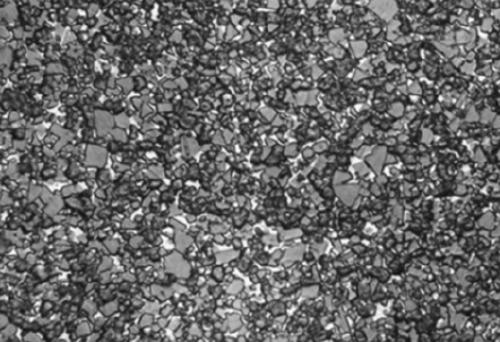
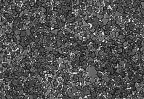
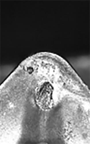

Image

  • Coating blade for steel component processing and preparing method thereof
  • Coating blade for steel component processing and preparing method thereof
  • Coating blade for steel component processing and preparing method thereof

Examples


Embodiment 1

[0034] This embodiment provides a method for preparing a coated blade for steel processing, comprising the following steps:

[0035] S1. Weigh Co, TaNb8, (W, Ti) CN and WC respectively, wherein the mass fraction of Co is 6.8%, the mass fraction of TaNb8 is 3%, (W, Ti) CN mass fraction is 5.1%, and the balance is WC;

[0036] S2. Mix the raw material weighed in step S1 with polyethylene glycol, the amount of polyethylene glycol is 2% of the mass of the raw material, pour it into a drum type ball mill for ball milling, the ball milling time is 24 hours, and the ball milling medium is alcohol;

[0037] S3. Dry, press, and sinter the mixture treated in step S2 to make a cemented carbide matrix blade. The sintering process is as follows: put the material in a sintering furnace with a hydrogen atmosphere, and heat up from 25°C to 180°C at a uniform speed in the first 30 minutes. Then the temperature was raised to 310°C at a constant speed for 30 minutes, then to 370°C at a constant...

Embodiment 2

[0040] This embodiment provides a method for preparing a coated blade for steel processing, comprising the following steps:

[0041] S1. Weigh Co, TaNb8, (W, Ti) CN and WC respectively, wherein the mass fraction of Co is 6.8%, the mass fraction of TaNb8 is 3%, (W, Ti) CN mass fraction is 5.1%, and the balance is WC;

[0042] S2. Mix the raw material weighed in step S1 with polyethylene glycol, the amount of polyethylene glycol is 2% of the mass of the raw material, pour it into a drum-type ball mill for ball milling, the ball milling time is 15 hours, and the ball milling medium is alcohol;

[0043]S3. Dry, press, and sinter the mixture treated in step S2 to make a cemented carbide matrix blade. The sintering process is as follows: put the material in a sintering furnace with a hydrogen atmosphere, and heat up from 25°C to 180°C at a uniform speed in the first 30 minutes. Then the temperature was raised to 310°C at a constant speed for 30 minutes, then to 370°C at a constant ...


PUM

PropertyMeasurementUnit
thicknessaaaaaaaaaa
thicknessaaaaaaaaaa
thicknessaaaaaaaaaa

Abstract

The invention relates to the field of cutting tools and particularly relates to a coating blade for steel component processing and a preparing method thereof. The coating blade for steel component processing comprises a cemented carbide base and a coating, wherein the thickness of a cubic-carbide-free layer on the cemented carbide base is 5-10mum. The preparing method of the coating blade for steel component processing comprises the following steps: after uniformly mixing Co, TaNb8, (W, Ti)CN, WC and a forming agent, pouring the mixture into a drum type ball mill to carry out ball milling; then, pressing and sintering the ball-milled mixture to make a blade with the cemented carbide base; and coating the blade with the cemented carbide base with the coating, and carrying out sand blastingtreatment to obtain the coating blade for steel component processing. The making technology of the coating blade for steel component processing, which is provided by the invention, is simple, the wearresistance of the blade is improved, crater wear can be effectively inhibited, and the production of built-up edges is reduced.

Description

technical field [0001] The invention relates to the field of coated blades, in particular to a coated blade for steel processing and a preparation method thereof. Background technique [0002] When machining and cutting steel parts, due to the high cutting resistance and high heat generated, the rake face is in a state of high temperature and high pressure, which will cause crater wear on the rake face of the blade and built-up edge at the tip of the blade. Crescent wear will affect the wear resistance of the blade and reduce the service life of the blade; the generation of built-up edge will affect the sharpness and surface finish of the blade, resulting in certain vibration during processing, affecting the surface quality and dimensional accuracy of the workpiece. The prior art has disclosed the method of sintering in nitrogen to improve the performance of cemented carbide, and improve the product's wear resistance and crater wear resistance. Nitrogen can be added to ceme...

Claims


Application Information

Patent Timeline
Patent Type & Authority Applications(China)
IPC IPC(8): B22F1/00B22F3/02B22F3/10B22F5/00C22C29/02C23C16/02C23C16/36C23C16/40C22C1/10C22C1/05
CPCC22C1/051C22C29/005C22C29/02C23C16/02C23C16/36C23C16/403B22F3/02B22F3/1025B22F5/00B22F1/10
Inventor 唐小强刘钢袁美和谭文清
Owner OKE PRECISION CUTTING TOOLS CO LTD
Learn More