Energy-efficient plasma electric welding machine device with magnetically stabilized arc

A plasma and magnetic stabilization technology, applied in the field of material processing, can solve the problems of insufficient arc column penetration, uneven weld thickness, unstable arc, etc., and achieve fast welding speed, less weld defects, and thin welding columns long effect

Inactive Publication Date: 2019-01-04
叶露穗
View PDF6 Cites 0 Cited by
  • Summary
  • Abstract
  • Description
  • Claims
  • Application Information

AI Technical Summary

Problems solved by technology

[0002] Plasma arc is the ionization of ionized gas to generate high-temperature ion airflow, which is ejected from the nozzle pores and compressed to form a slender arc column. The ion welding machine operates according to this principle. The current ion welding machine is unstable due to the current. The arc is unstable, so that the penetration of the arc column is not strong enough during welding, and the thickness of the weld is not uniform

Method used


Image

  • Energy-efficient plasma electric welding machine device with magnetically stabilized arc
  • Energy-efficient plasma electric welding machine device with magnetically stabilized arc

Examples


Embodiment 1

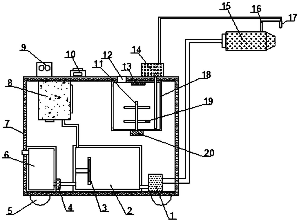
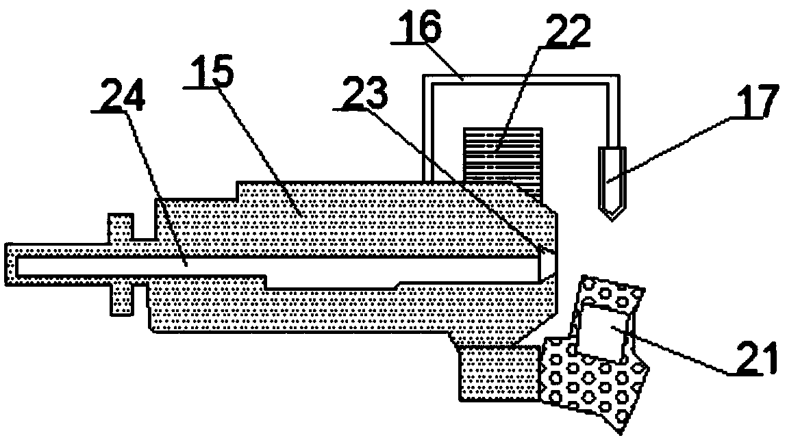
[0022] Such as Figure 1-2 As shown, an energy-efficient plasma welding machine with a magnetically stable arc includes a main body box 7, a nozzle body 15, and a gas mixing chamber 2. The inner bottom of the main body box 7 is provided with a gas mixing chamber 2, and the gas mixing chamber 2 A gas booster pump 1 is installed on one side through a mounting piece, and an argon gas storage chamber 6 is arranged at one end of the inner bottom of the main body box 7, and an air pump 4 is installed on one side of the argon gas storage room 6 through a mounting bracket. 7. The inner top is connected with a hydrogen generator 8 through a connecting frame and the output end of the hydrogen generator 8 is connected to the gas mixing chamber 2 through a pipeline. One side of the hydrogen generator 8 is provided with a feed chamber 18, and the bottom of the feed chamber 18 is A motor 20 is installed by bolts, an infrared heating tube 13 is installed on the top of the feed chamber 18 thr...

Embodiment 2

[0036] Such as Figure 1-2As shown, an energy-efficient plasma welding machine with a magnetically stable arc includes a main body box 7, a nozzle body 15, and a gas mixing chamber 2. The inner bottom of the main body box 7 is provided with a gas mixing chamber 2, and the gas mixing chamber 2 A gas booster pump 1 is installed on one side through a mounting piece, and an argon gas storage chamber 6 is arranged at one end of the inner bottom of the main body box 7, and an air pump 4 is installed on one side of the argon gas storage room 6 through a mounting bracket. 7. The inner top is connected with a hydrogen generator 8 through a connecting frame and the output end of the hydrogen generator 8 is connected to the gas mixing chamber 2 through a pipeline. One side of the hydrogen generator 8 is provided with a feed chamber 18, and the bottom of the feed chamber 18 is A motor 20 is installed by bolts, an infrared heating tube 13 is installed on the top of the feed chamber 18 thro...


PUM


Abstract

The invention discloses an energy-efficient plasma electric welding machine device with the magnetically stabilized arc, including a body box, a spray head main body and a gas mixing chamber. The gasmixing chamber is arranged at the bottom of the body box, a gas pressurizing pump is installed on one side of the gas mixing chamber through a mounting piece, an argon storage chamber is arranged at one end of the inner bottom of the body box, an air pump is installed at one side of the argon storage chamber through a mounting bracket, a hydrogen generator is connected with the inner top of the body box through a connecting frame and an output end of the hydrogen generator is connected with the air mixing chamber through a pipe, a feeding chamber is arranged on one side of the hydrogen generator, a motor is installed at the bottom of the feeding chamber through bolts, and an infrared heating pipe is installed at the top part of the feeding chamber through a connecting seat. As the arc reaches a magnetically stable state, a welding column is thin and long, the penetration force is strong, the weld speed is fast, the welding seam defects are few, and the welding quality is high.

Description

technical field [0001] The invention relates to the technical field of material processing, in particular to an energy-efficient plasma welding machine with a magnetically stable arc. Background technique [0002] Plasma arc is the ionization of ionized gas to generate high-temperature ion airflow, which is ejected from the nozzle pores and compressed to form a slender arc column. The ion welding machine operates according to this principle. The current ion welding machine is unstable due to the current. As a result, the arc is unstable, so that the penetration of the arc column is not strong enough during welding, and the thickness of the weld is not uniform. To this end, we propose an energy-efficient plasma welder device with a magnetically stabilized arc. Contents of the invention [0003] The main purpose of the present invention is to provide an energy-efficient plasma welding machine with a magnetically stable arc, which can effectively solve the problems in the ba...

Claims


Application Information

Patent Timeline
Patent Type & Authority Applications(China)
IPC IPC(8): B23K10/02
CPCB23K10/02
Inventor 叶露穗
Owner 叶露穗
Why Eureka
Try Eureka