Welding structure and welding method of a water cooling system

A welding structure and water cooling technology, applied in welding equipment, high-frequency current welding equipment, household refrigeration devices, etc., can solve problems such as unfavorable welding material protection, easy change, stress deformation, etc., to improve structural stability and product quality. Longevity, reduced oxygen partial pressure, and reduced thermal stress

Active Publication Date: 2021-02-19
NINGBO RAREMAT INC
View PDF7 Cites 0 Cited by
  • Summary
  • Abstract
  • Description
  • Claims
  • Application Information

AI Technical Summary

Problems solved by technology

In the existing technology, the two ports of the water pipe and the welding plug are restricted by the material of the weldment, the structure of the weldment and the welding technology, and become the place where water leakage is most likely to occur
Under high temperature and high pressure environment, the internal structure of the material of the existing weldment is easy to change, and the stress in the non-horizontal or vertical direction will cause deformation and damage, which is not conducive to the protection of the weldment material

Method used


Image

  • Welding structure and welding method of a water cooling system
  • Welding structure and welding method of a water cooling system
  • Welding structure and welding method of a water cooling system

Examples


Embodiment Construction

[0037] The following will clearly and completely describe the technical solutions in the embodiments of the present invention with reference to the accompanying drawings in the embodiments of the present invention. Obviously, the described embodiments are only some, not all, embodiments of the present invention. Based on the embodiments of the present invention, all other embodiments obtained by persons of ordinary skill in the art without making creative efforts belong to the protection scope of the present invention.

[0038] In order to make the above objects, features and advantages of the present invention more comprehensible, the present invention will be further described in detail below in conjunction with the accompanying drawings and specific embodiments.

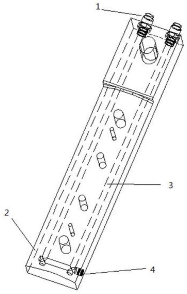
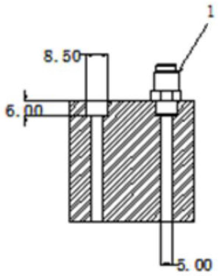
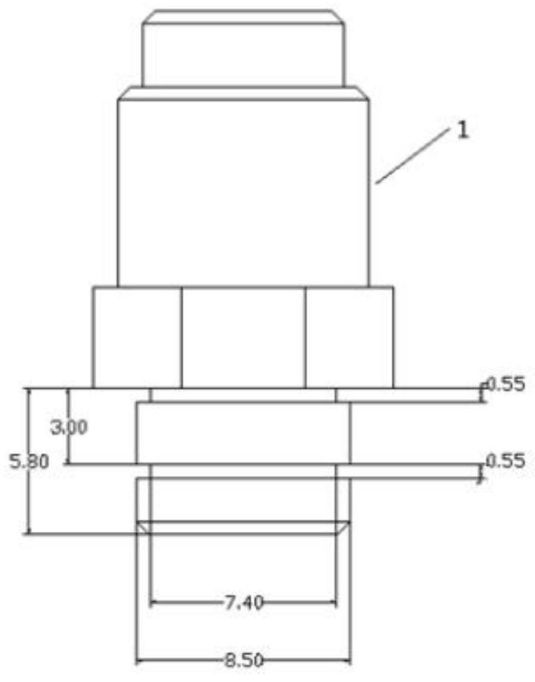
[0039] like Figure 1-5 As shown, the welded structure of the water cooling system provided in this embodiment includes a welded part 2, a water-cooled pipeline 3 arranged inside the welded part 2, a joint 1 arran...


PUM

PropertyMeasurementUnit
lengthaaaaaaaaaa

Abstract

The invention discloses a welding structure and a welding method of a water cooling system. The welding structure comprises a welding piece, a water cooling pipeline arranged inside the welding piece,a joint arranged between an inlet end of the water cooling pipeline and a cold water inlet pipe, and a plug arranged at an outlet end of the water cooling pipeline. The welding structure adopts the welding piece, the joint and the plug which are special and welded together, so that the purpose of low leakage rate of the water cooling pipeline under the high temperature and high pressure environment is realized.

Description

technical field [0001] The invention relates to the field of welding technology, in particular to a welding structure and a welding method of a water cooling system. Background technique [0002] Water cooling is the most commonly used cooling and heat dissipation method in actual production. The basic principle is that a water-cooling pipeline is installed on the surface of the heating equipment, and one end of the water-cooling pipeline is injected with cold water, and the cold water quickly flows through the water-cooling tube under the action of high pressure. The heat generated by a part of the equipment is taken away, and it flows out at the other end and is cooled and then injected into the water-cooling pipeline to form a circulating water cooling system. [0003] The existing water-cooling system generally achieves symmetrical distribution and arrangement of water-cooling pipelines along the heating equipment, and uses conventional welding machines to weld joints an...

Claims


Application Information

Patent Timeline
Patent Type & Authority Patents(China)
IPC IPC(8): B23K13/06F25D1/02
CPCB23K13/06F25D1/02
Inventor 施惠栋任秀江
Owner NINGBO RAREMAT INC
Why Eureka
Try Eureka