Automatic laying production line and control method of wind turbine blade root preform

A preform and automatic laying technology, which is applied in the automatic laying production line and control field of wind power blade root preforms, can solve the problems of increasing the production time of wind power blade root preforms and reducing production efficiency, and achieves the goal of reducing interlayer wrinkles Probability, improvement of production efficiency, and improvement of molding quality

Pending Publication Date: 2019-01-04
NEWTRY COMPOSITE
View PDF6 Cites 3 Cited by
  • Summary
  • Abstract
  • Description
  • Claims
  • Application Information

AI Technical Summary

Problems solved by technology

[0002] The root of the wind turbine blade is composed of a cylinder, so each piece of fabric is composed of a standard rectangle, but the length of each piece of fabric is different. The traditional production method is to manually stack the cut fabrics one by one according to

Method used


Image

  • Automatic laying production line and control method of wind turbine blade root preform
  • Automatic laying production line and control method of wind turbine blade root preform
  • Automatic laying production line and control method of wind turbine blade root preform

Examples


Embodiment 1

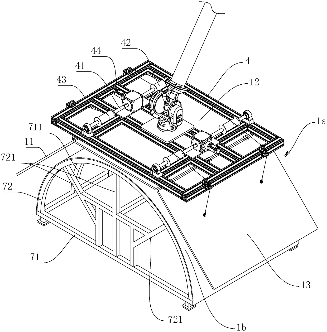
[0048] Embodiment 1: An automatic laying production line for wind power blade root preforms, including a cutting station for carrying and cutting cloth; a conveying device for conveying the cloth on the cutting station; variant structure 1 for preforming Deformation and forming of molded parts.

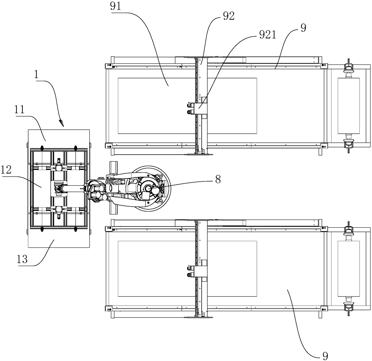
[0049] like figure 1As shown, the cutting station includes one or more than one cutting platform 9. In this embodiment, there are two cutting platforms 9. The cutting platform 9 is equipped with a belt transmission structure, which drives the cloth to move to the cutting area. 91. The cutting platform 9 is equipped with a gantry 92 , and the gantry 92 performs linear reciprocating motion along the length direction of the cutting platform 9 . A cutting machine 921 is installed on the gantry 92, and the cutting machine 921 performs linear reciprocating motion along the length direction of the gantry 92. The structure of the linear reciprocating motion can be realized by a screw struct...

Embodiment 2

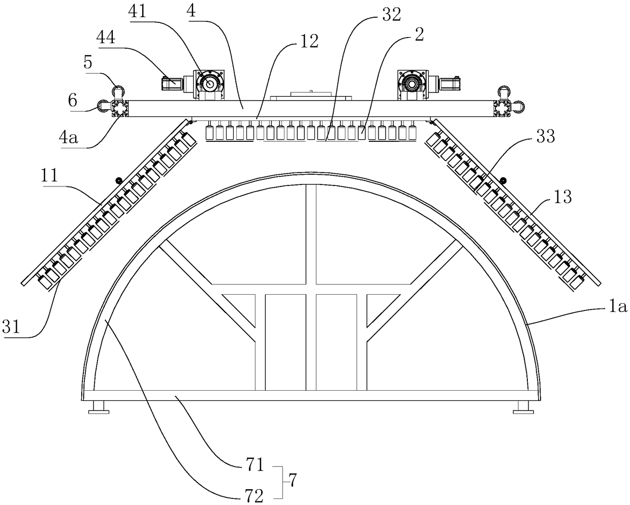
[0059] Embodiment 2: A control method for an automatic laying production line of wind power blade root preforms, such as Figure 1 to Figure 3 shown, including the following steps:

[0060] 1.1 Unwinding: the unwinding device actively unwinds the fabric forward, the distance between the end of the cutting platform 9 away from the modified structure 1 and the unwinding shaft forms the fabric storage section, and the conveyor belt of the cutting platform 9 rotates to drive the fabric Move forward to the cutting area 91;

[0061] 1.2 Cutting: Through the calculation of the size of the figure to be cut, the cutting machine 921 corresponds to the coordinates of the cloth in the cutting area 91 according to the shape of the figure to be cut, so that the center point of the circumscribed rectangle of the figure to be cut falls on the center line of the cutting area 91 , cut the fabric along each cutting line of the graphics to be cut;

[0062] 1.3 Deformation of the cloth frame bod...


PUM


Abstract

The invention discloses an automatic laying production line and a control method of wind turbine blade root perform, and belongs to the field of laying equipment. The production line comprises a cutting station, a conveying device and a variant structure, wherein the variant structure comprises a cloth take-up frame body and a semicircular molding surface; the cloth take-up frame body comprises afirst frame body, a second frame body and a third frame body; two ends of the second frame body are respectively hinged with the first frame body and the third frame body; needling sucking discs are arranged on the lower sides of the first frame body, the second frame body and the third frame body and form a first adsorption plane, a second adsorption plane and a third adsorption plane; when clothis absorbed by the cloth take-up frame body, the first adsorption plane and the third adsorption plane synchronously rotate reversely upwards around a hinge point until the first adsorption plane, the second adsorption plane and the third adsorption plane are at the same height; when the cloth is molded by the cloth take-up frame body, the first adsorption plane and the third adsorption plane synchronously rotate reversely downwards around the hinge point. According to the production line, preforms can be molded one by one, the probability of occurrence of interlayer folds among the preformsis reduced, and the production efficiency is improved.

Description

technical field [0001] The invention relates to automatic laying equipment, in particular to an automatic laying production line and control method for wind power blade root preforms. Background technique [0002] The root of the wind turbine blade is composed of a cylinder, so each piece of fabric is composed of a standard rectangle, but the length of each piece of fabric is different. The traditional production method is to manually stack the cut fabrics one by one according to the length of the fabric. Semicircular mold After that, the stacked semicircular preforms are placed on the injection mold by a crane, and the two semicircular preforms are bonded by glue to form a cylindrical blade root. The production time of the root preform reduces the production efficiency. [0003] In view of the above technical problems, based on years of rich practical experience and professional knowledge engaged in the engineering application of such products, and with the application of ...

Claims


Application Information

Patent Timeline
IPC IPC(8): B29C70/38
CPCB29C70/386
Inventor 钮青谈源周瑞陈玉祥陈香伟
Owner NEWTRY COMPOSITE
Why Eureka
Try Eureka